Compliant microfluidic sample processing disks

a processing disk and microfluidic technology, applied in the field of microfluidic sample processing disks, can solve the problems of inaccurate or inaccurate control of chamber-to-chamber temperature uniformity, time-consuming and expensive individual processing, misleading or inaccurate control, etc., to improve the flexibility of the disk, reduce the amount of body material, and ensure compliance and flexibility

Active Publication Date: 2007-01-11
DIASORIN ITALIA SPA
View PDF99 Cites 71 Cited by
  • Summary
  • Abstract
  • Description
  • Claims
  • Application Information

AI Technical Summary

Benefits of technology

[0012] One potential advantage of some of the microfluidic sample processing disks of the present invention may include, e.g., process chambers arranged in a compliant annular processing ring that is adapted to conform to the shape of an underlying thermal transfer surface under pressure. That compliance may be delivered in the disks of the present invention by, e.g., locating the process chambers in an annular processing ring in which a majority of the volume is occupied by the process chambers which are preferably formed by voids extending through the body of the disks. In such a construction, limited amounts of the body forming the structure of the disk are present within the annular processing ring, resulting in improved flexibility of the disk within the annular processing ring. Further compliance and flexibility may be achieved by locating orphan chambers within the annular processing ring, the orphan chambers further reducing the amount of body material present in the annular processing ring.
[0013] Other optional features that may improve compliance within the annular processing ring may include a composite structure within the annular processing ring that includes covers attached to a body using pressure sensitive adhesive that exhibits viscoelastic properties. The viscoelastic properties of pressure sensitive adhesives may allow for relative movement of the covers and bodies during deformation or thermal expansion / contraction while maintaining fluidic integrity of the fluid structures in the sample processing disks of the present invention.
[0014] The use of covers attached to a body as described in connection with the sample processing disks of the present invention may also provide advantages in that the properties of the materials for the different covers and bodies may be selected to enhance performance of the disk.
[0016] Another property that may preferably be exhibited by some of the covers used in connection with the present invention is thermal conductivity. Using materials for the covers that enhance thermal conductivity may improve thermal performance where, e.g., the temperature of the sample materials in the process chambers are preferably heated or cooled rapidly to selected temperatures or where close temperature control is desirable. Examples of materials that may provide desirable thermal conductive properties may include, e.g., metallic layers (e.g., metallic foils), thin polymeric layers, etc.
[0018] As discussed above, if the materials used for the covers are too extensible, they may bulge or otherwise distort at undesirable levels during, e.g., rotation of the disk, heating of materials within the process chambers, etc. One potentially desirable combination of properties in the covers used to construct process chambers of the present invention may include relative inextensibility, transmissivity to electromagnetic energy of selected wavelengths, and thermal conductivity. Where each process chamber is constructed by a void in the central body and a pair of covers on each side, one cover may be selected to provide the desired transmissivity and inextensibility while the other cover may be selected to provide thermal conductivity and inextensibility. One suitable combination of covers may include, e.g., a polyester cover that provides transmissivity and relative inextensibility and a metallic foil cover that provides thermal conductivity and inextensibility on the opposite side of the process chamber. Using pressure sensitive adhesive to attach relatively inextensible covers to the body of the disks may preferably improve compliance and flexibility by allowing relative movement between the covers and the body that may not be present in other constructions.

Problems solved by technology

Although it may be possible to process samples individually and obtain accurate sample-to-sample results, individual processing can be time-consuming and expensive.
When multiple reactions are performed in different chambers, however, one significant problem can be accurate control of chamber-to-chamber temperature uniformity.
Temperature variations between chambers may result in misleading or inaccurate results.
In reactions involving a change in temperature, the speed or rate at which the temperature changes in each of the chambers may also pose a problem.
For example, slow temperature transitions may be problematic if unwanted side reactions occur at intermediate temperatures.
Alternatively, temperature transitions that are too rapid may cause other problems.
As a result, another problem that may be encountered is comparable chamber-to-chamber temperature transition rate.
In addition to chamber-to-chamber temperature uniformity and comparable chamber-to-chamber temperature transition rate, another problem may be encountered in those reactions in which thermal cycling is required is overall speed of the entire process.
In some reactions, e.g., polymerase chain reaction (PCR), thermal cycling must be repeated up to thirty or more times. Thermal cycling devices and methods that attempt to address the problems of chamber-to-chamber temperature uniformity and comparable chamber-to-chamber temperature transition rates, however, typically suffer from a lack of overall speed—resulting in extended processing times that ultimately raise the cost of the procedures.
When using the traditional equipment according to the traditional methods, the high thermal mass of the thermal cycling equipment (which typically includes the metal block and a heated cover block) and the relatively low thermal conductivity of the polymeric materials used for the microcuvettes result in processes that can require two, three, or more hours to complete for a typical PCR amplification.
This approach does not, however, address the thermal cycling issues such as the high thermal mass of the metal block and heated cover or the relatively low thermal conductivity of the polymeric materials used to form the card.
In addition, the thermal mass of the integrating card structure can extend thermal cycling times. Another potential problem of this approach is that if the card containing the sample wells is not seated precisely on the metal block, uneven well-to-well temperatures can be experienced, causing inaccurate test results.
Yet another problem that may be experienced in many of these approaches is that the volume of sample material may be limited and / or the cost of the reagents to be used in connection with the sample materials may also be limited and / or expensive.
When using small volumes of these materials, however, additional problems related to the loss of sample material and / or reagent volume through vaporization, etc. may be experienced as the sample materials are, e.g., thermally cycled.
Another problem that may be experienced in the preparation of finished samples (e.g., isolated or purified samples of, e.g., nucleic acid materials such as DNA, RNA, etc.) of human, animal, plant, or bacterial origin from raw sample materials (e.g., blood, tissue, etc.) is the number of thermal processing steps and other methods that must be performed to obtain the desired end product (e.g., purified nucleic acid materials).
In addition to suffering from the thermal control problems discussed above, all or some of these processes may require the attention of highly skilled professionals and / or expensive equipment.
In addition, the time required to complete all of the different process steps may be days or weeks depending on the availability of personnel and / or equipment.

Method used


Image

  • Compliant microfluidic sample processing disks
  • Compliant microfluidic sample processing disks
  • Compliant microfluidic sample processing disks

Examples


Embodiment Construction

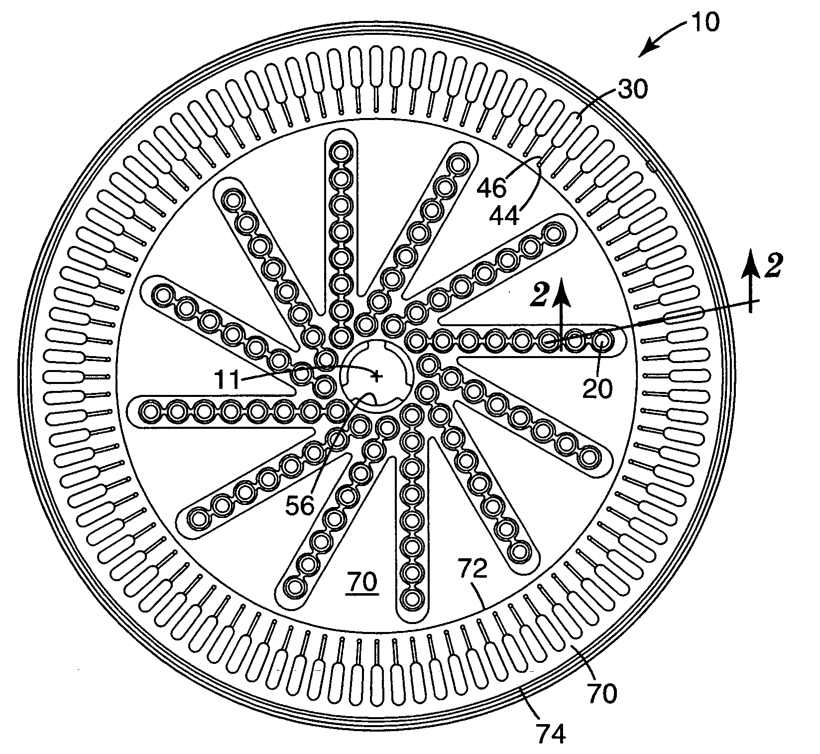
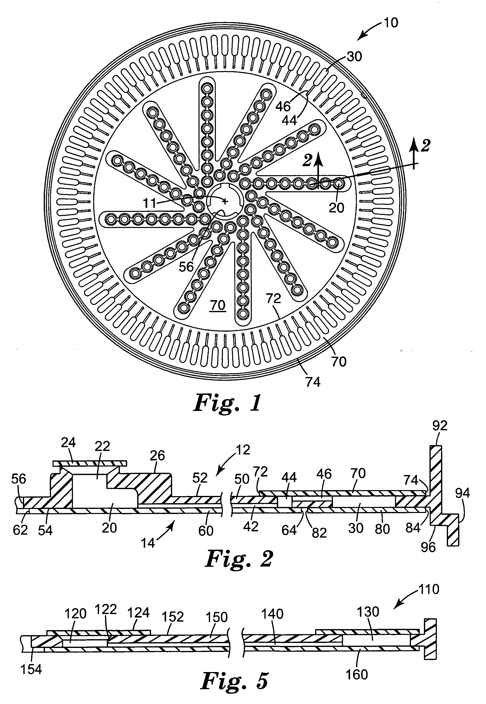
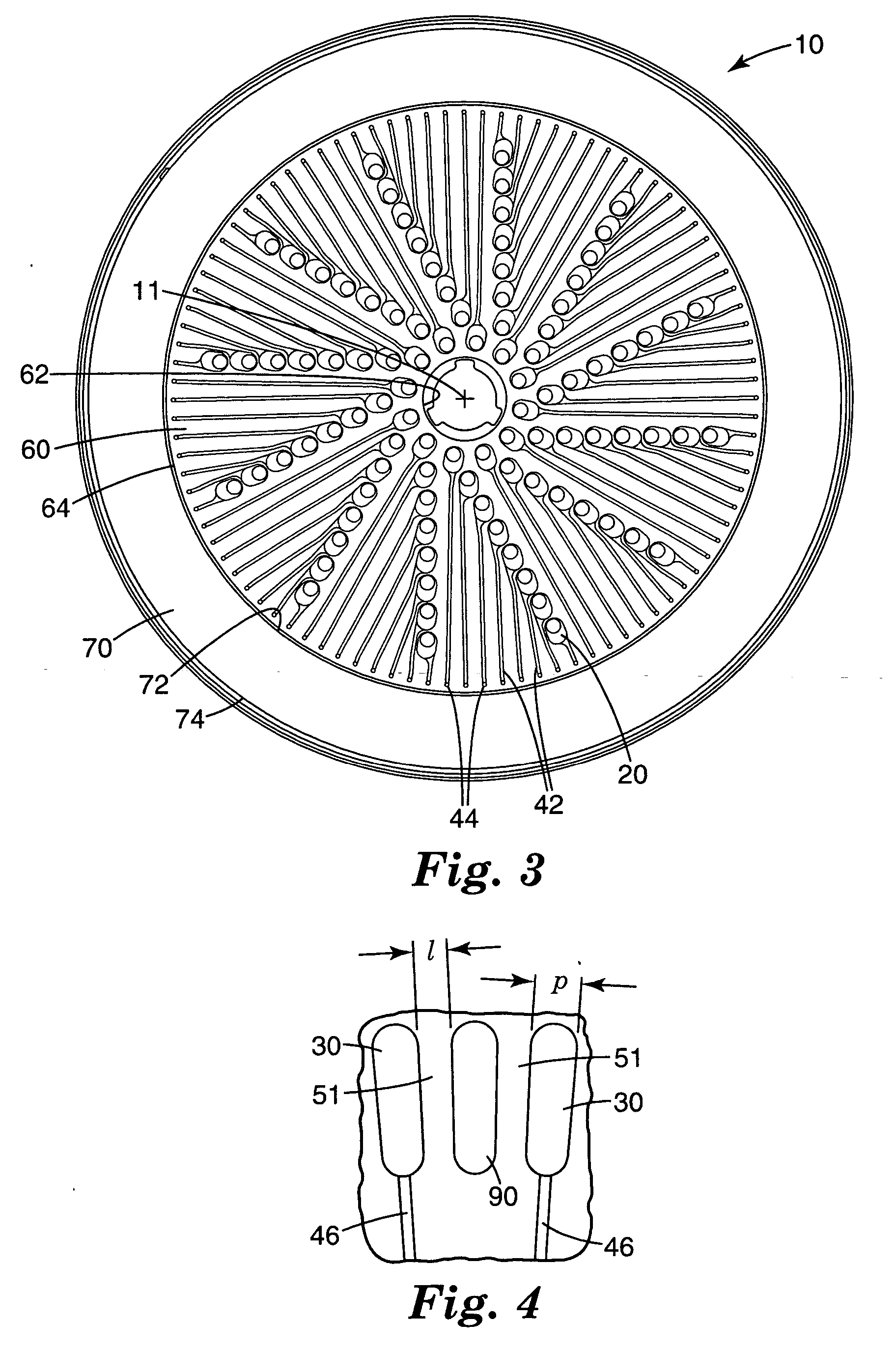
[0032] In the following description of exemplary embodiments of the invention, reference is made to the accompanying figures of the drawing which form a part hereof, and in which are shown, by way of illustration, specific embodiments in which the invention may be practiced. It is to be understood that other embodiments may be utilized and structural changes may be made without departing from the scope of the present invention.

[0033] The present invention provides microfluidic sample processing disks and methods for using them that involve thermal processing, e.g., sensitive chemical processes such as PCR amplification, ligase chain reaction (LCR), self-sustaining sequence replication, enzyme kinetic studies, homogeneous ligand binding assays, and more complex biochemical or other processes that require precise thermal control and / or rapid thermal variations. The sample processing disks are preferably capable of being rotated while the temperature of sample materials in process cha...


PUM


Abstract

Microfluidic sample processing disks with a plurality of fluid structures formed therein are disclosed. Each of the fluid structures preferably includes an input well and one or more process chambers connected to the input well by one or more delivery channels. The process chambers may be arranged in a compliant annular processing ring that is adapted to conform to the shape of an underlying thermal transfer surface under pressure. That compliance may be delivered in the disks of the present invention by locating the process chambers in an annular processing ring in which a majority of the volume is occupied by the process chambers. Compliance within the annular processing ring may alternatively be provided by a composite structure within the annular processing ring that includes covers attached to a body using pressure sensitive adhesive.

Description

[0001] The present invention relates to the field of microfluidic sample processing disks used to process samples that may contain one or more analytes of interest. [0002] Many different chemical, biochemical, and other reactions are sensitive to temperature variations. Examples of thermal processes in the area of genetic amplification include, but are not limited to, Polymerase Chain Reaction (PCR), Sanger sequencing, etc. The reactions may be enhanced or inhibited based on the temperatures of the materials involved. Although it may be possible to process samples individually and obtain accurate sample-to-sample results, individual processing can be time-consuming and expensive. [0003] One approach to reducing the time and cost of thermally processing multiple samples is to use a device including multiple chambers in which different portions of one sample or different samples can be processed simultaneously. When multiple reactions are performed in different chambers, however, one ...

Claims


Application Information

Patent Timeline
Patent Type & Authority Applications(United States)
IPC IPC(8): B01L3/00
CPCB01L3/502715B01L3/502738B01L7/52B01L2200/027B01L2300/1805B01L2300/044B01L2300/0803B01L2300/0887B01L2200/0689B01J19/00B01L3/00
Inventor BEDINGHAM, WILLIAMROBOLE, BARRY W.
Owner DIASORIN ITALIA SPA
Why Eureka
Try Eureka