Organic electroluminescent element and display device or light emitting device equipped with the same

a technology of electroluminescent elements and light emitting devices, which is applied in the direction of discharge tube luminescnet screens, natural mineral layered products, transportation and packaging, etc., can solve the problems of shortening the life of organic el elements and negatively affecting the electron transport layer of organic materials, so as to reduce the number of electrons, reduce the lumo energy level, and reduce the deterioration of the hole transport layer including the amine derivative due to electrons

a technology of electroluminescent elements and light emitting devices, which is applied in the direction of discharge tube luminescnet screens, natural mineral layered products, transportation and packaging, etc., can solve the problems of shortening the life of organic el elements and negatively affecting the electron transport layer of organic materials, so as to reduce the number of electrons, reduce the lumo energy level, and reduce the deterioration of the hole transport layer including the amine derivative due to electrons

US20070009762A1Active Publication Date: 2007-01-11SANYO ELECTRIC CO LTD

Image

  • Organic electroluminescent element and display device or light emitting device equipped with the same
  • Organic electroluminescent element and display device or light emitting device equipped with the same
  • Organic electroluminescent element and display device or light emitting device equipped with the same

Examples


example 1

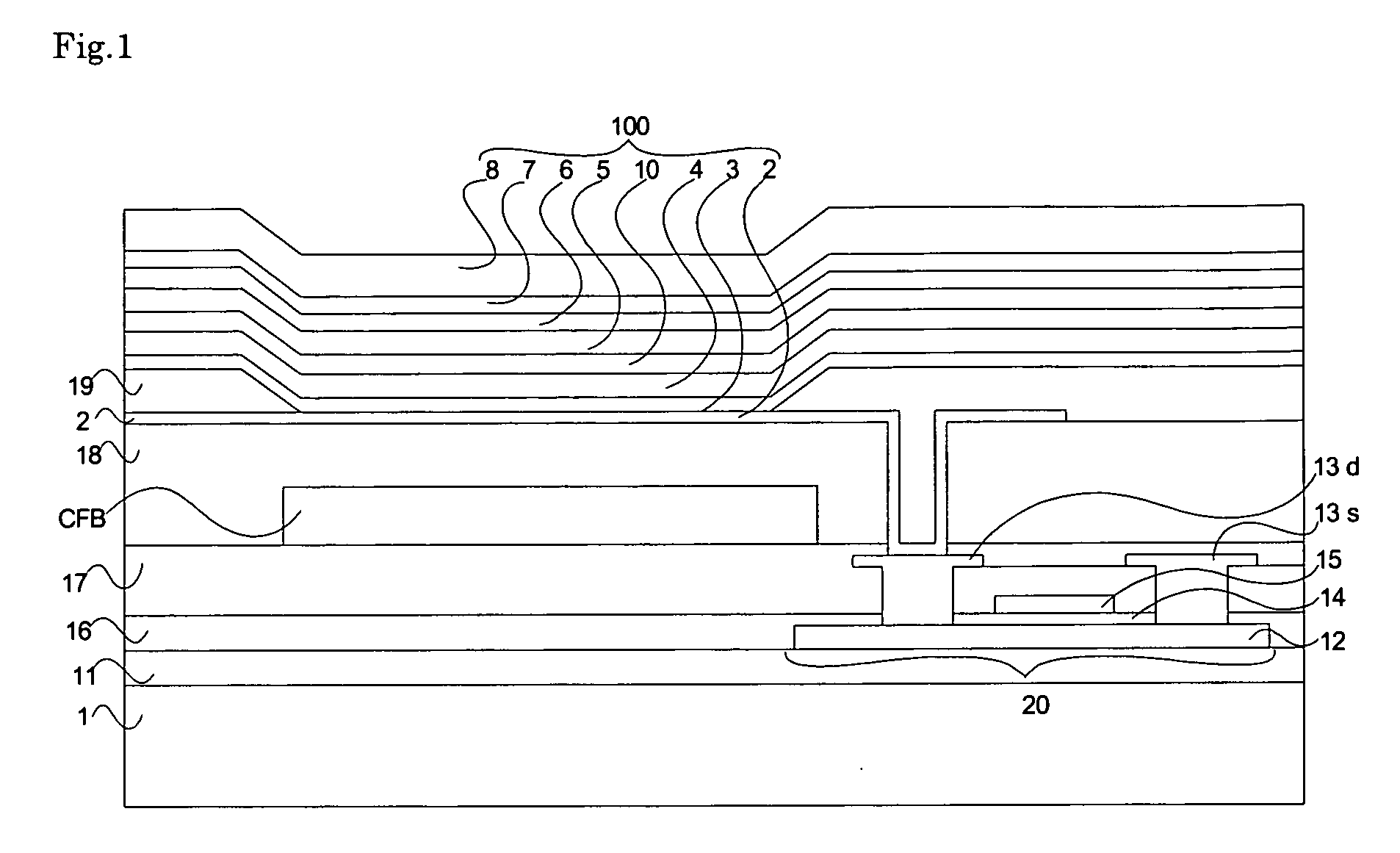
[0090] In Example 1, an organic EL element having the structure shown in FIG. 1 was fabricated as follows.

[0091] An indium tin oxide (ITO) layer was formed on the substrate 1 made of glass, followed by the formation of a CFx (carbon fluoride) layer on the ITO layer by a plasma CVD method, whereby the anode 2 having a double layer structure comprised of the ITO and carbon fluoride layers was formed. A plasma discharge time in the plasma CVD was 15 seconds in this case.

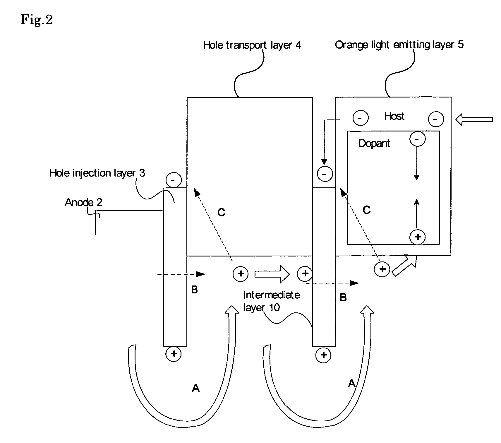
[0092] Further, onto the anode 2, the hole injection layer 3, hole transport layer 4, intermediate layer 10, orange light emitting layer 5, blue light emitting layer 6 and electron transport layer 7 were sequentially formed by vacuum evaporation.

[0093] The hole injection layer 3 is comprised of HAT-CN6 having a film thickness of 10 nm. The hole transport layer 4 is comprised of NPB having a film thickness of 100 nm. The intermediate layer 10 is comprised of HAT-CN6 having a film thickness of 10 nm, similarly to the h...

example 2

[0097] In Example 2, an organic EL element same as that in Example 1 was prepared, except that a film thickness of NPB used as the hole transport layer 4 was 150 nm.

example 3

[0098] In Example 3, an organic EL element same as that in Example 1 was prepared, except that a film thickness of NPB used as the hole transport layer 4 was 80 nm.


PUM

PropertyMeasurementUnit
energy levelaaaaaaaaaa
LUMOaaaaaaaaaa
wavelengthaaaaaaaaaa

Abstract

It is an object of the present invention to provide an organic electroluminescent element having a longer lifetime. In order to accomplish the object, an organic electroluminescent element adapted to comprise a light emitting layer including an organic material between an anode and a cathode is provided with a hole transport layer for transporting holes injected from the anode toward the light emitting layer. Along with the hole transport layer, an intermediate layer having an energy level of a lowest unoccupied molecular orbital lower than those of the hole transport layer and the light emitting layer is provided therebetween.

Description

TECHNICAL FIELD [0001] The present invention relates to an organic electroluminescent element and a display device or a light emitting device equipped with the element. BACKGROUND OF INVENTION [0002] In recent years, with the diversification of information equipment, demands for a flat-panel display element that enables lower power consumption compared to a generally used CRT (cathode-ray tube) have been increasing. As one of such flat-panel display elements, an organic electroluminescent element (hereinafter referred to as an ā€œorganic EL elementā€) characterized by high-efficiency, flat-shape, lightweight, and low dependence on a view angle is attracting attentions. [0003] A currently well-known organic EL element has a layered structure in which between a hole injection electrode (anode) and an electron injection electrode (cathode), a hole transport layer for transporting holes injected from the anode, a light emitting layer for emitting light by facilitating to recombine holes tr...

Claims


Application Information

Patent Timeline
11 Jan 2007
Publication
US20070009762A1
IPC
H01L51/54; H05B33/12
CPC
C09K11/06; C09K2211/1007; C09K2211/1011; C09K2211/1037; H01L51/0054; Y10T428/24942; H01L51/0072; H01L51/0081
Inventors
HAMADA, YUJI; HASHIMOTO, HARUHISA