Tissue retractor and method for using the retractor

Inactive Publication Date: 2007-01-11
ID LLC (US)
View PDF3 Cites 29 Cited by
  • Summary
  • Abstract
  • Description
  • Claims
  • Application Information

AI Technical Summary

Benefits of technology

[0010] It is accordingly an object of the present invention to provide a tissue retractor and method for using the retractor that overcome the hereinafore-mentioned disadvantages of the heretofore-known devices and methods of this general type and that can effectively grab the tissue, for example, of the alimentary tract during operation and avoid reaching into the serosa, and that can grab the tissue without compressing and/or tearing the tissue.
[0011] Various endoscopic procedures require manipulation of specific layers in the gastric wall. For instance, in the case of mucosal resection, the mucosa is tented away from the muscularis and resected away. Such a procedure is currently performed by injecting fluid beneath the mucosa to, thus, lift the mucosa from the muscularis. The mucosal tissue is, then, resected using electrocautery. The tissue retractor of the present invention can be used to selectively grasp the mucosa and lift it from the muscularis, thus enabling and simplifying mucosal resection. In the case of forming a full thickness plication in the stomach, the stronger muscular layer of the gastric wall must be grasped to ensure that the full thickness of the wall will be retracted when forming the plication.

Problems solved by technology

The mucosa is a relatively thin layer, loosely attached to the muscularis, and retraction of the mucosa only will not provide a sufficient plication for insertion of a fastener for the treatment of GERD.
One of the most significant reasons is that an unsealed perforation of the serosa, if sufficiently large, could

Method used


Image

  • Tissue retractor and method for using the retractor
  • Tissue retractor and method for using the retractor
  • Tissue retractor and method for using the retractor

Examples


second embodiment

[0116]FIGS. 10 through 25 illustrate a flexible tissue retractor according to the invention.

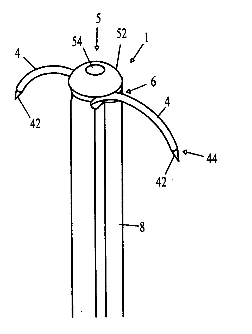
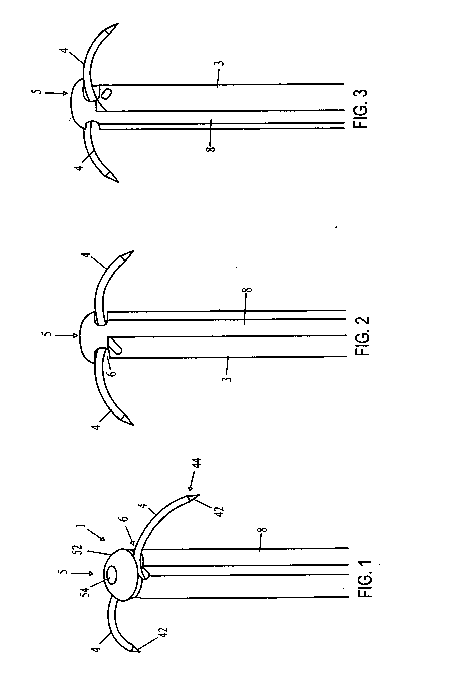
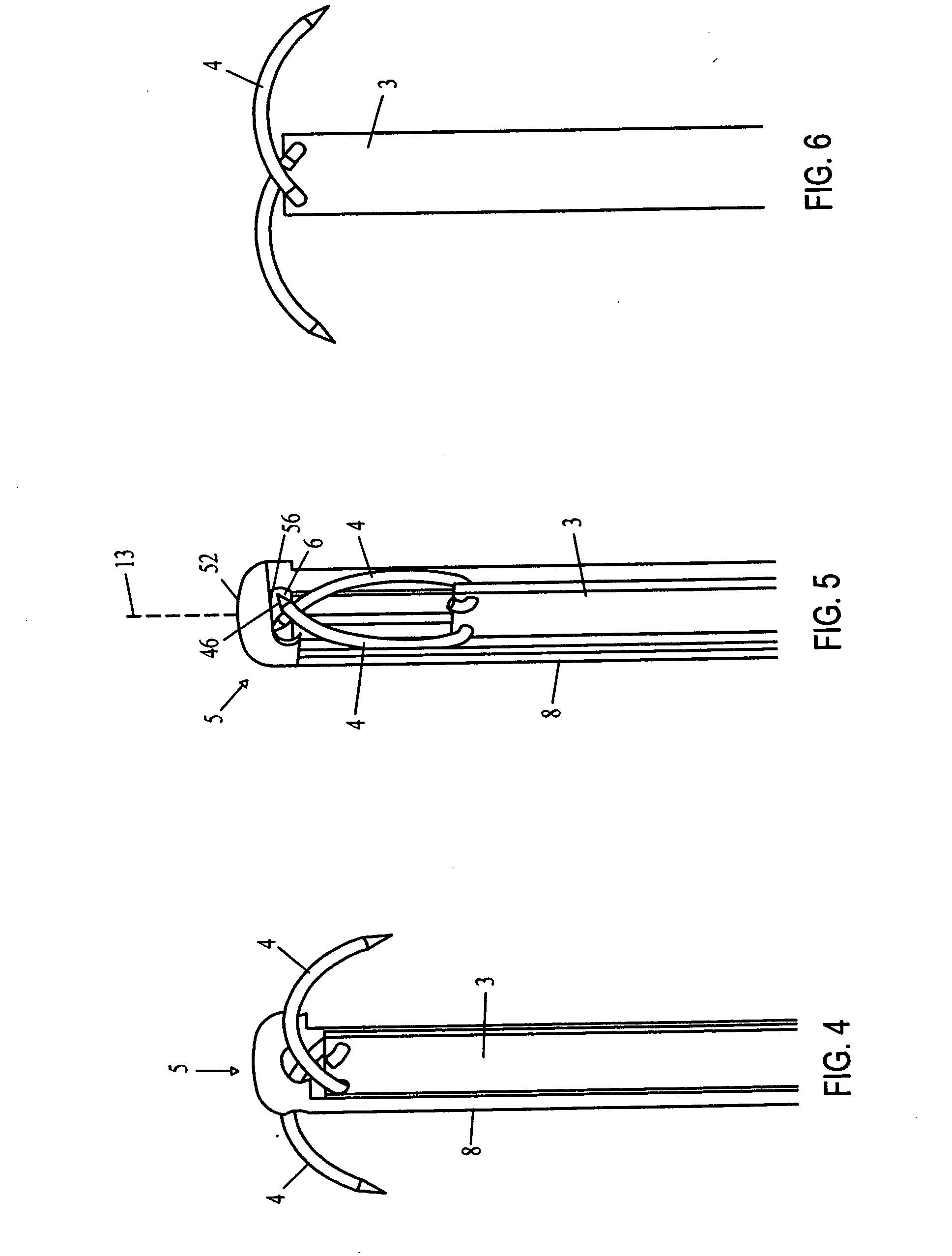
[0117] A distal tip 5 is assembled at a distal end of an outer jacket 8 (shown only diagrammatically with dashed lines). Preferably, the distal tip 5 is fastened to the distal end of the outer jacket 8. For example, the distal tip 5 can have a mushroom-shape with a head 51 and a cylindrical body 52 radially smaller than the head 51. The body 52 can be slidably inserted into the hollow distal end of the outer jacket 8 and fastened thereto using any fastening measure. For example, the body 52 can be welded, heat-shrunk, melted, or glued into the outer jacket 8 or the body can have a male thread that is screwed into a female thread disposed on the interior surface of distal end of the outer jacket 8. The connection may be reversed as well.

[0118] The distal tip 5 may be formed, for example, as a single piece or from two half-pieces secured together. If the distal tip 5 is constructed from two ha...

third embodiment

[0136]FIGS. 27 through 46 illustrate a flexible tissue retractor according to the invention.

[0137] A distal tip 5 is assembled at a distal end of an outer jacket 8 (shown only diagrammatically with dashed lines). Preferably, the distal tip 5 is fastened to the distal end of the outer jacket 8. For example, the distal tip 5 can have a mushroom-shape with a head 51 and a cylindrical body 52 radially smaller than the head 51. The body 52 can be slidably inserted into the hollow distal end of the outer jacket 8 and fastened thereto using any fastening measure. For example, the body 52 can be welded, heat-shrunk, melted, or glued into the outer jacket 8 or the body can have a male thread that is screwed into a female thread disposed on the interior surface of distal end of the outer jacket 8. The connection may be reversed as well.

[0138] The distal tip 5 may be formed, for example, as a single piece or from two half-pieces secured together. If the distal tip 5 is constructed from two ha...

fourth embodiment

[0158]FIGS. 47 through 56 illustrate a flexible tissue retractor according to the invention.

[0159] A distal tip 5 is assembled at a distal end of an outer jacket 8 (shown only diagrammatically with dashed lines). Preferably, the distal tip 5 is fastened to the distal end of the outer jacket 8. For example, as shown in FIG. 54, the distal tip 5 can have a mushroom-shaped bottom 52 with a cylindrical body 51 radially smaller than the bottom 52. The bottom 52 can be slidably inserted onto the hollow distal end of the outer jacket 8 and fastened thereto using any fastening measure. For example, the bottom 52 can be welded, heat-shrunk, melted, or glued onto the outer jacket 8 or the bottom 52 can have a male thread that is screwed into a female thread disposed on the exterior surface of distal end of the outer jacket 8. The distal tip 5 may be formed, for example, as a single piece or from two half-pieces secured together. If the distal tip 5 is constructed from two halves, then they ca...


PUM


Abstract

A retractor for manipulating an object includes a body having proximal and distal ends, a retraction device, and an actuation device. The retraction device has a head connected to the distal end of the body, substantially rigid needles, and an actuator. The head has a pivot. The needles are pivotally connected to the head about the pivot. The actuator is operatively connected to the needles and is movably disposed within the head and/or the body. The actuation device is connected to the proximal end of the body. The actuation device is operatively connected to the actuator through the body and, upon actuation thereof, moves the actuator to selectively rotate the needles between a stowed position where the needles are stowed within the head and a fully extended position where the needles are extended out of the head.

Description

CROSS-REFERENCE TO RELATED APPLICATION [0001] This application claims the benefit under 35 U.S.C. § 119(e) of U.S. provisional applications Nos. 60 / 431,083, 60 / 505,009, 60 / 505,010, 60 / 640,684, filed Dec. 5, 2002, Sep. 22, 2003, and Dec. 30, 2004, and is a continuation in part of copending U.S. patent application Ser. No. 10 / 252,079, filed Sep. 20, 2002 and entitled “Surgical Fastener Particularly for the Treatment of Gastroesophageal Reflux Disease (GERD),” is a continuation in part of copending U.S. patent application Ser. No. 10 / 252,069, filed Sep. 20, 2002, and entitled “Instrument for Applying a Surgical Fastener Particularly for the Transoral Treatment of Gastroesophageal Reflux Disease (GERD),” is a continuation in part of copending U.S. patent application Ser. No. 10 / 252,078, filed Sep. 20, 2002, and entitled “Method for the Surgical Application of a Fastener and the Endoluminal Treatment of Gastroesophageal Reflux Disease (GERD),” is a continuation in part of copending U.S. ...

Claims


Application Information

Patent Timeline
IPC IPC(8): A61B1/32
CPCA61B17/0218A61B17/0643A61B17/068A61B2017/2927A61B2017/00292A61B2017/00827A61B2017/047A61B17/29
Inventor SIXTO, ROBERT JR.KORTENBACH, JUERGENMARTIN, CHRISPINOS, JORGE
Owner ID LLC (US)
Why Eureka
Try Eureka