Control system for internal combustion engine

a control system and internal combustion engine technology, applied in the direction of electrical control, process and machine control, instruments, etc., can solve the problems of increasing the calculation load on the control apparatus and affecting the control performance, and achieve the effect of preventing the ignition timing from deviating

Inactive Publication Date: 2007-01-18
HONDA MOTOR CO LTD
View PDF7 Cites 21 Cited by
  • Summary
  • Abstract
  • Description
  • Claims
  • Application Information

AI Technical Summary

Benefits of technology

[0011] With the above-described configuration, the learning value of the ignition delay is calculated. The fuel injection timing correction amou

Problems solved by technology

For example, if the cylinder pressure is to be detected during comparatively short periods of time and control is to be performed based on the detection results, the calculation l

Method used


Image

  • Control system for internal combustion engine
  • Control system for internal combustion engine
  • Control system for internal combustion engine

Examples


Embodiment Construction

[0024] Preferred embodiments of the present invention will now be described with reference to the drawings.

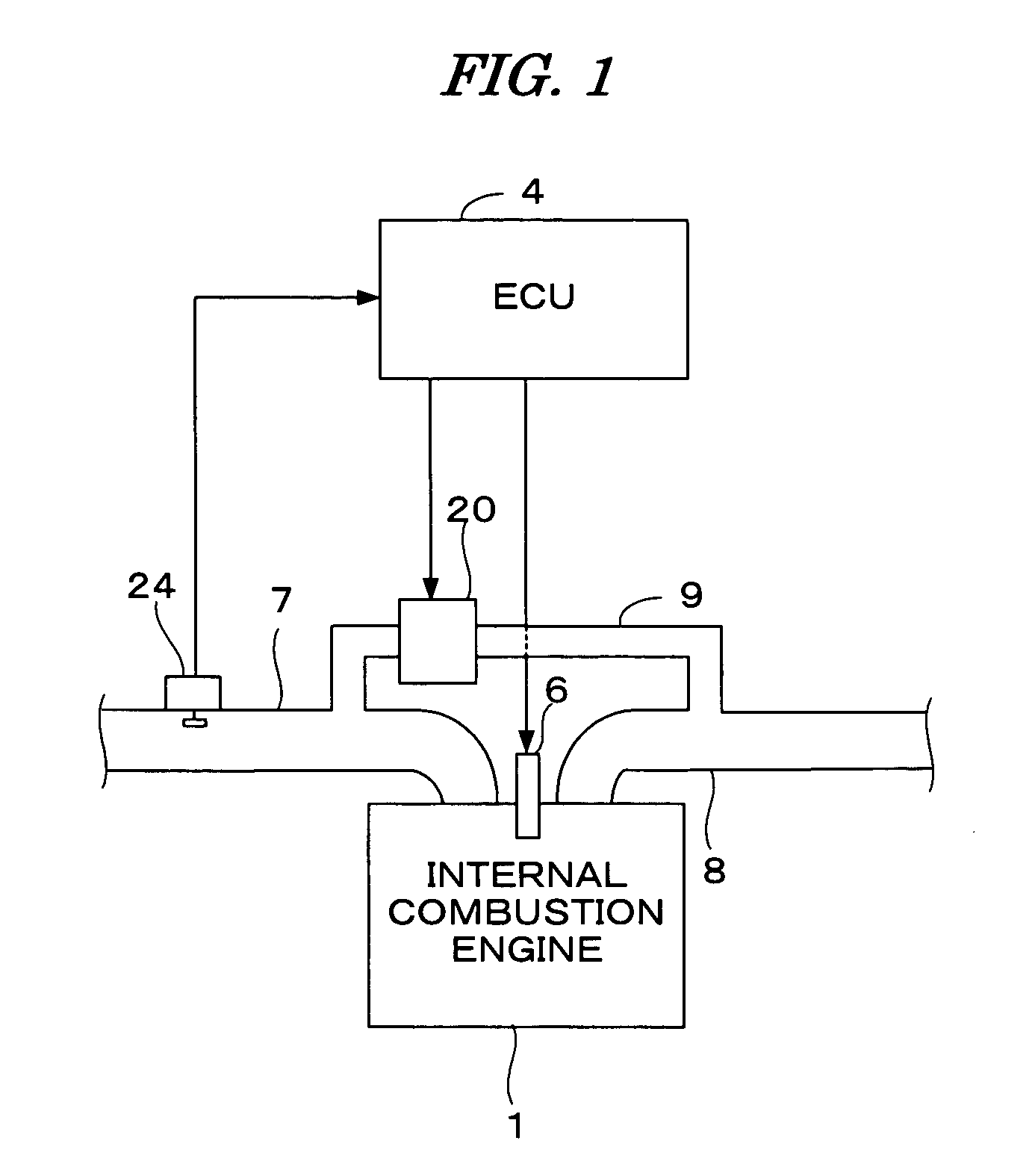
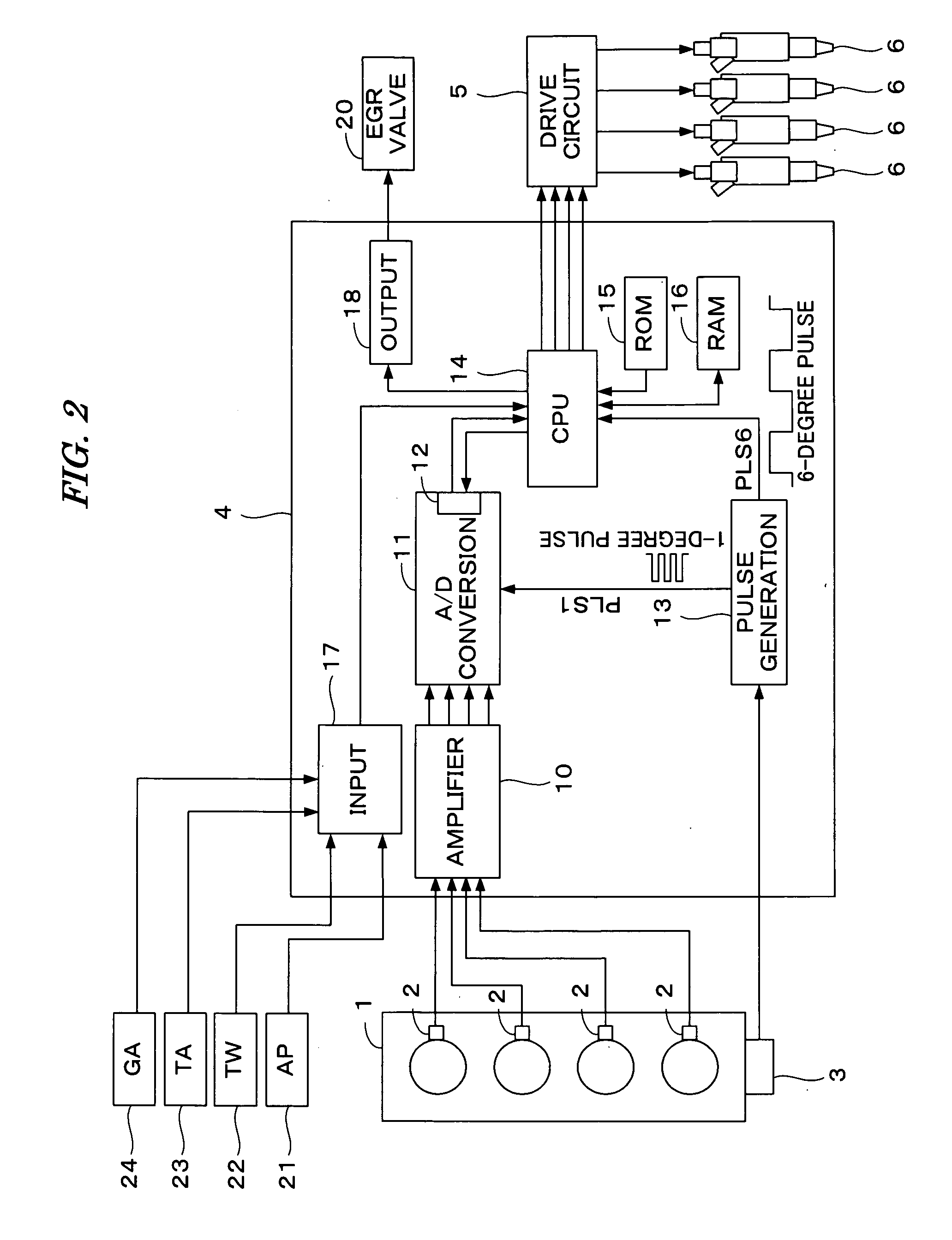
[0025]FIGS. 1 and 2 are schematic diagrams illustrating a configuration of an internal combustion engine and a control system therefor according to one embodiment of the present invention. The internal combustion engine 1 (hereinafter referred to as “engine”), which has four cylinders, is a diesel engine, wherein fuel is injected directly into the cylinders. Each cylinder is provided with a fuel injection valve 6 that is electrically connected to an electronic control unit 4 (hereinafter referred to as “ECU 4”). The ECU 4 controls a valve opening period and a valve opening timing of each fuel injection valve 6. That is, the fuel injection period and fuel injection timing are controlled by the ECU 4.

[0026] The engine 1 has an intake pipe 7 and an exhaust pipe 8. An exhaust gas recirculation passage 9 for recirculating a part of exhaust gases to the intake pipe 7 is provided be...


PUM


Abstract

A control system for an internal combustion engine having a fuel injector located in a combustion chamber of the engine for injecting fuel into the combustion chamber. The fuel injection timing stored in a fuel injection timing map is retrieved according to the detected engine operating condition to determine the fuel injection timing. An actual ignition timing of the fuel injected into the combustion chamber is detected. An ignition delay of the actual ignition timing with respect to the target ignition timing, which is set according to the engine operating condition and a fuel injection timing correction amount, is calculated according to the calculated ignition delay. The fuel injection timing is corrected with the fuel injection timing correction amount, and the fuel injection is executed according to the corrected fuel injection timing.

Description

BACKGROUND OF THE INVENTION [0001] 1. Field of the Invention [0002] The present invention relates to a control system for an internal combustion engine, and particularly, to a system for controlling an internal combustion engine according to a pressure in the cylinder detected by a cylinder pressure sensor. [0003] 2. Description of the Related Art [0004] Japanese Patent Laid-open No. 2004-100566 (JP '566) discloses a fuel injection control apparatus in which the cylinder pressure (pressure in the combustion chamber) is detected by a cylinder pressure sensor, and a fuel injection amount, a fuel injection timing, and the like, are controlled according to the detected cylinder pressure. According to the disclosed apparatus, the crank angle Cmax at which the cylinder pressure reaches a maximum value is detected, and the fuel injection timing is corrected so that the detected crank angle Cmax coincides with a target value which is previously set according to the engine operating conditio...

Claims


Application Information

Patent Timeline
IPC IPC(8): F02P5/00F02M51/00G06F17/00
CPCF02D35/023F02D41/0055F02D41/005F02D41/0052F02D41/2461F02D41/345F02D2041/1409F02D2041/141F02D2041/1431F02D2200/0402F02D2200/0612F02P5/1527Y02T10/44F02D35/028F02D37/02Y02T10/40
Inventor YAMAGUCHI, SATOSHISHIMASAKI, YUICHIHASEGAWA, MAMORU
Owner HONDA MOTOR CO LTD
Why Eureka
Try Eureka