Apparatus and method for downstream pressure control and sub-atmospheric reactive gas abatement

a technology of atmospheric reactive gas and apparatus, applied in mechanical apparatus, transportation and packaging, coatings, etc., can solve the problems of clogging the valve, affecting the flow rate of the valve, and the performance of the mechanical throttle valve is prone to deterioration, so as to optimize the flow rate and speed up the response. , the effect of smooth flow

Inactive Publication Date: 2007-01-18
SUNDEW TECH
View PDF11 Cites 348 Cited by
  • Summary
  • Abstract
  • Description
  • Claims
  • Application Information

AI Technical Summary

Benefits of technology

[0020] It is the objective of the present invention to provide a method for downstream pressure control with fast response. It is another objective of our invention to provide apparatus and method for performing downstream pressure control without...

Problems solved by technology

However, downstream pressure control and foreline effluent management continue to be maintenance intensive and performance-limiting bottlenecks.
Unfortunately, the mechanical throttle valve is prone for deteriorated performance under most common usage due to the growth of solid deposits on mechanical moving parts.
These deposits can clog the valve or impede the mechanical motion that is necessary for adequate performance.
In addition, the mechanical motion breaks-off deposits and is prone to make particles that are detrimental to process yield.
Throttle valves produce flow turbulences that sometimes affect the process adversely and are further notorious for dislodging particles from the throttle valve vicinity.
In addition, the response of throttle valves to pressure fluctuations is often too slow and tends to develop oscillatory response that impact process results disadvantageously.
The outcomes of throttle valve oscillatory response are disadvantageous process pressure fluctuations and back-flow from the throttle valve area carrying dislodged particles into the process space.
However, pressure control performance was inferior to the throttle valve method.
In particular, time response of gas ballast technique was inadequately slow.
A disadvantageous and inevitable composition change of inflow gas mixture renders this technique inadequate for most CVD and etch processes and for the majority of reactive sputtering processes.
As upstream controlled pressure was deemed inadequate for CVD and etch processes in the prior art, it is not surprising that the method of injecting “ballast” gas upstream to the throttle valve did not produce an improvement to prior art.
However, this method did not produce an improved method for downstream pressure control.
A close look at the method of injecting ballast gas downstream from a throttle and into the inlet of a turbomolecular pump reveals that the method is based on controlling the pumping speed of the pump by forcing the pump into a disadvantageous high-load regime where the pumping speed strongly depends on the inflow (pump “choking” mode).
Accordingly, a maximum pressure of 10 mTorr at the pump inlet does not provide a substantial impact on the flow through a throttle valve during typical low pressure CVD (LPCVD) and etch processes.
In this range the pump behaves disadvantageously with characteristics such as slo...

Method used


Image

  • Apparatus and method for downstream pressure control and sub-atmospheric reactive gas abatement
  • Apparatus and method for downstream pressure control and sub-atmospheric reactive gas abatement
  • Apparatus and method for downstream pressure control and sub-atmospheric reactive gas abatement

Examples


embodiment 700

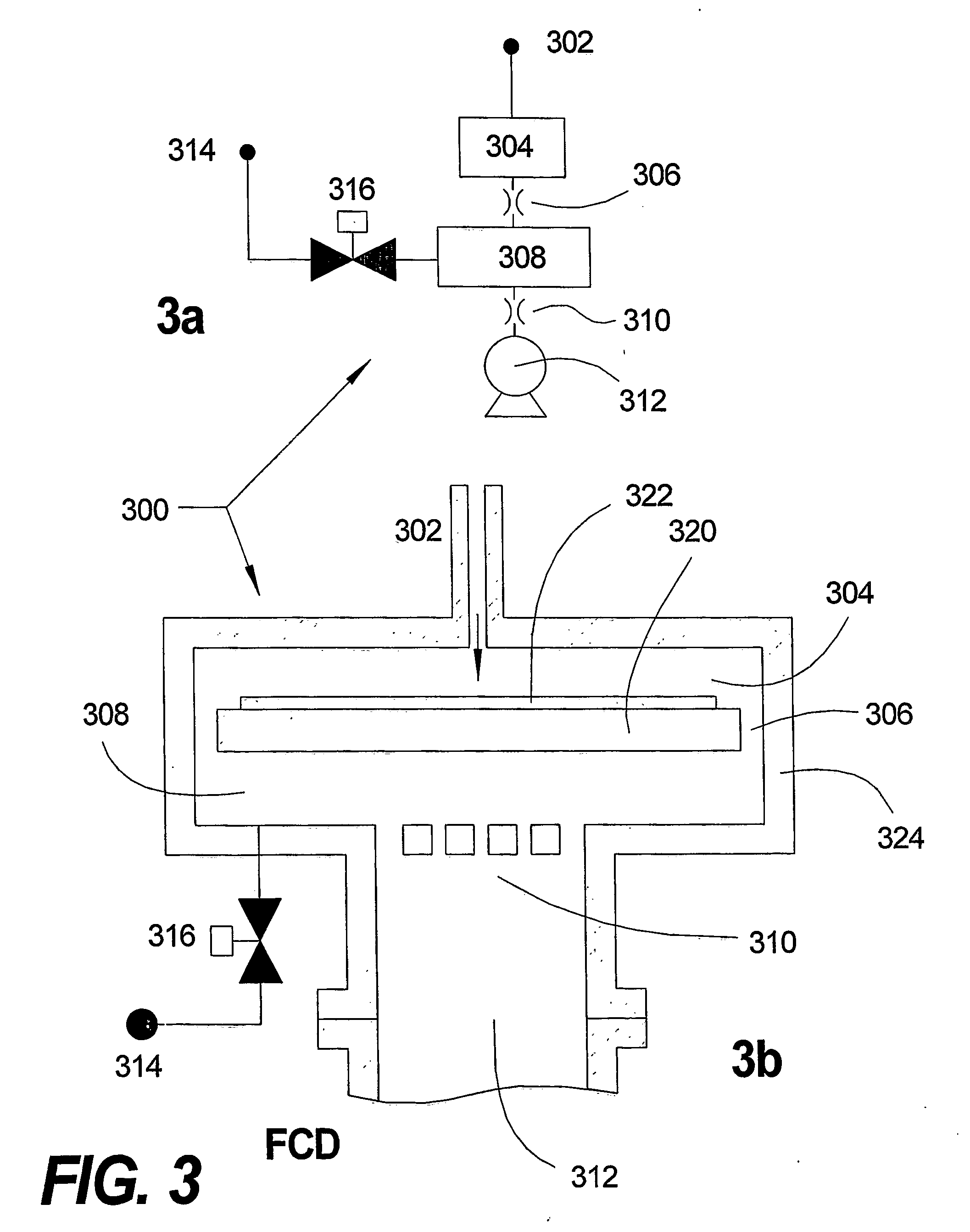
[0096] Higher capacity for abatement of chemicals such as TEOS can be achieved by another preferred embodiment, 700, depicted in FIG. 8. For example, FIG. 8 implements the PCC similar to the embodiment depicted in FIG. 3 and described with reference to FIG. 3. Accordingly, PCC 308 is implemented as a compartment within vessel 324. PCC 308 may include an abatement element (not shown). In addition or as an alternative, the abatement is carried further downstream within abatement chamber 740. Adverse effluent reaction and solid film deposition in the foreline leading to abatement chamber 740 is suppressed by wall-protected conduit elements. For example, 3 elements, 710, 720 and 730 are depicted in FIG. 8. For example the wall protected elements are implemented as described with reference to FIG. 4, above. Pumps and additional downstream foreline are represented schematically by 750. According to preferred embodiment 700 abatement can include larger volume of chamber 740 with higher aba...

embodiment 800

[0097] In another example of the preferred embodiment, 800, (FIG. 9) a much higher abatement capacity is implemented downstream from a batch processing reactor such as a vertical furnace LPCVD reactor. Reactor 802 is connected through FRE 804 to PCC 806 for FCD downstream pressure control in accordance with the present invention. Process pressure is controlled by the flow of gas from source 810 through a proportional valve (or valves arrangement as described above with reference to the inset in FIG. 2) 812. Effluents exit PCC 806 through FRE 808 into wall protected conduit 820 (shown only schematically) and enter abatement chamber 826 though isolation gatevalve 822 and FRE 824. Reactive gasses are supplied to abatement chamber 826, for example from sources 832 and through valves 834. The exhaust gas further exit abatement chamber 826 through FRE 828 and isolation gatevalve 830. Additional foreline 840 and pumps 842 are shown only schematically. In embodiment 800, very large capacity...


PUM

PropertyMeasurementUnit
Pressureaaaaaaaaaa

Abstract

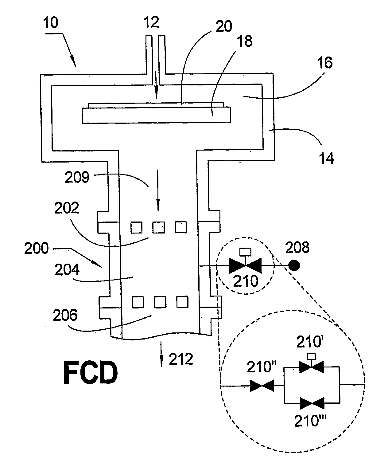
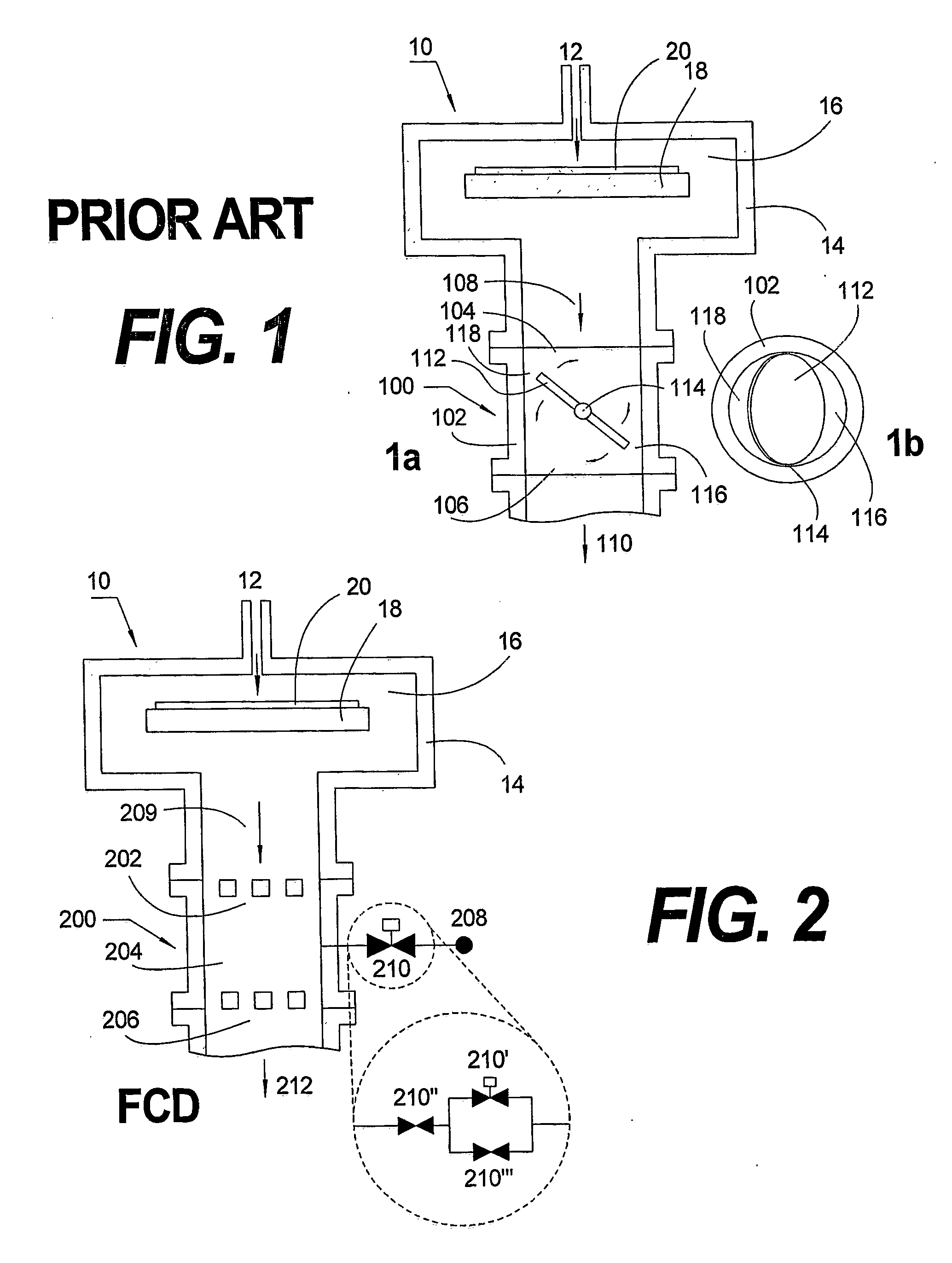
A sub-atmospheric downstream pressure control apparatus (200) includes a first flow restricting element (FRE) (202); a pressure control chamber (PCC) (204) located in serial fluidic communication downstream from the first FRE; a second FRE (206) located in serial fluidic communication downstream from the PCC; a gas source (208); and a flow controlling device (210) in serial fluidic communication downstream from the gas source and upstream from the PCC.

Description

BACKGROUND OF THE INVENTION [0001] 1. Field of the Invention [0002] This invention relates to the area of substrate processing and more specifically to apparatus and method for controlling pressure during deposition or etching processes and for effectively removing reactive chemicals from exhaust gas streams. [0003] 2. Description of Prior Art [0004] Low-pressure process systems are implemented extensively for semiconductor processing such as chemical vapor deposition (CVD) and etch. Typically these systems must employ both upstream effluent flow control and downstream pressure control to achieve satisfactory results. The technology of upstream effluent flow control is satisfactory and historically has never been a performance or cost bottleneck. However, downstream pressure control and foreline effluent management continue to be maintenance intensive and performance-limiting bottlenecks. Upstream manifolds need only to handle pure gasses within small diameter lines and relatively h...

Claims


Application Information

Patent Timeline
IPC IPC(8): F17D1/16H01L21/306C23C16/44C23C16/455
CPCC23C16/45557C23C16/4412Y10T137/0396
Inventor SNEH, OFER
Owner SUNDEW TECH
Why Eureka
Try Eureka