Electrical fan

a technology of electric fans and fan blades, which is applied in the direction of positive displacement liquid engines, liquid fuel engines, piston pumps, etc., can solve the problems of difficult modification, increased cooling fan size, and difficult to increase the size and shape of the stator core, so as to reduce the flow resistance of airflow, increase the size of the cooling fan, and generate a larger amount of airflow

Inactive Publication Date: 2007-01-18
FU ZHUN PRECISION IND SHENZHEN +1
View PDF9 Cites 40 Cited by
  • Summary
  • Abstract
  • Description
  • Claims
  • Application Information

AI Technical Summary

Benefits of technology

[0007] According to a preferred embodiment of the present invention, an electrical fan comprises a fan housing having a central tube, a bearing received in the central tube, a stator mounted around the central tube, and a rotor being rotatably supported by the bearing in the central tube. The housing defines an air inlet and an air outlet at two different sides thereof. The stator and the rotor expand radially along a direction from the air inlet to the air outlet. The stator has a stator core which is made by powder sintering technology. The fan blades of the rotor have a larger size and thus can generate a larger amount of airflow. The hub of the rotor has a streamline shaped outer surface with the smallest diameter adjacent to the air inlet of the fan; the flowing resistance of the airflow is reduced and the turbulence flow and noise are generally avoided. Finally a larger amount of airflow with increased speed and pressure is generated, and the heat dissipating effectiveness of the electrical fan is improved.

Problems solved by technology

However, this way will increase the size of the cooling fan, which is disadvantageous in view of miniaturization requirement of electronic products.
However, the yokes of the stator core 62 are formed by stamping silicon-steel sheets, each of which has a flat configuration and a predetermined diameter; thus, the size and the shape of the stator core 62 are almost fixed and difficult be altered.
Furthermore, the flat, disc-shaped top wall 81 of the hub 82 forms a barrier for the airflow through the fan, whereby flow rate of the airflow is adversely affected.
Accordingly, the airflow provided by the conventional electrical fan cannot efficiently dissipate heat absorbed by a heat sink from a heat-generating electronic component away from the heat sink.

Method used


Image

  • Electrical fan
  • Electrical fan
  • Electrical fan

Examples


second embodiment

[0023]FIG. 6 illustrates an alternative embodiment of the present invention. Except for the stator 650 and rotor 670, other parts of the cooling fan in accordance with this second embodiment have substantially the same configuration with the cooling fan of the previous first preferred embodiment. In this embodiment, the stator core of the stator 650 has a shape of a truncated cone. The hub 671 and the permanent magnet 673 of the rotor 670 each has a truncated-conical shape generally corresponding to that of the stator core. The volume of the truncated-cone shaped hub 71 is approximately ⅓ of that of the hub of the conventional electrical fan. Thus the fan blades 675 have a larger size and can generate an airflow with a higher flow rate.

third embodiment

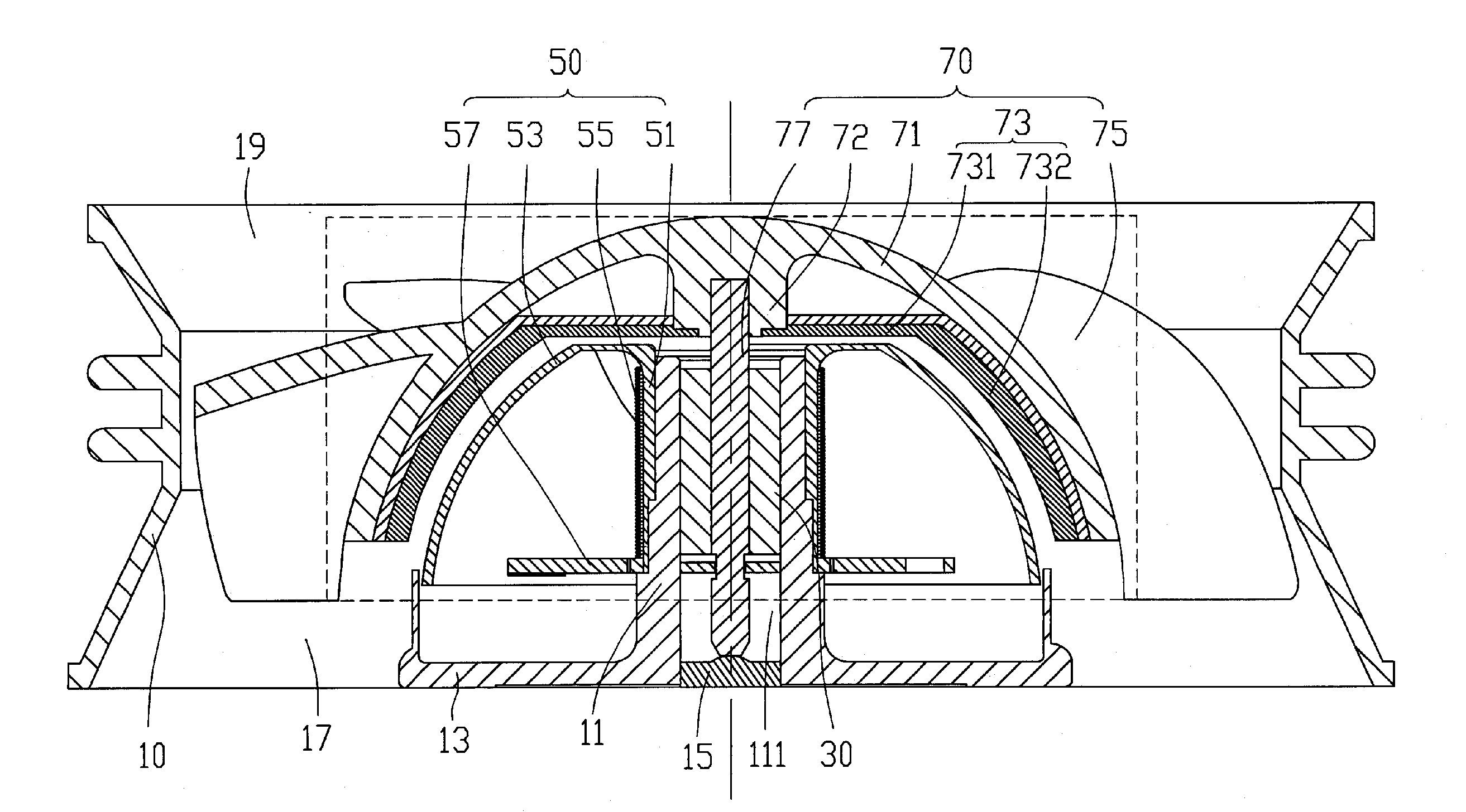
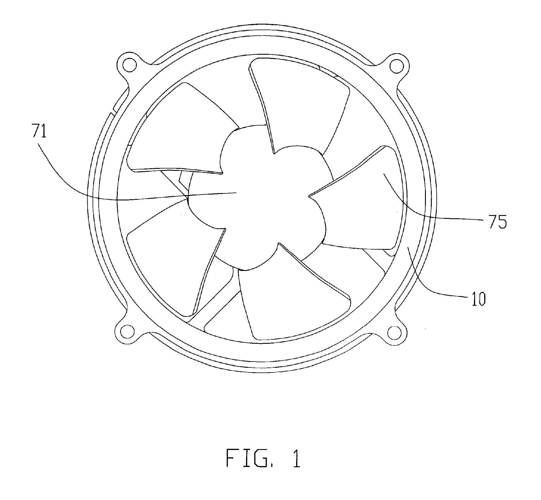
[0024] Referring to FIG. 7, it illustrates an electrical cooling fan in accordance with the present invention. In this embodiment, the hub 771 of the rotor 770 has a configuration of a hemi-ellipsoid. The stator 750 has a shape corresponding to the rotor 770. In this design, the volume of the hub 771 can be further decreased, whilst the size of the fan blades 775 further increases. Also the fan blades 775 of the rotor 770 can generate a relatively larger amount of airflow.

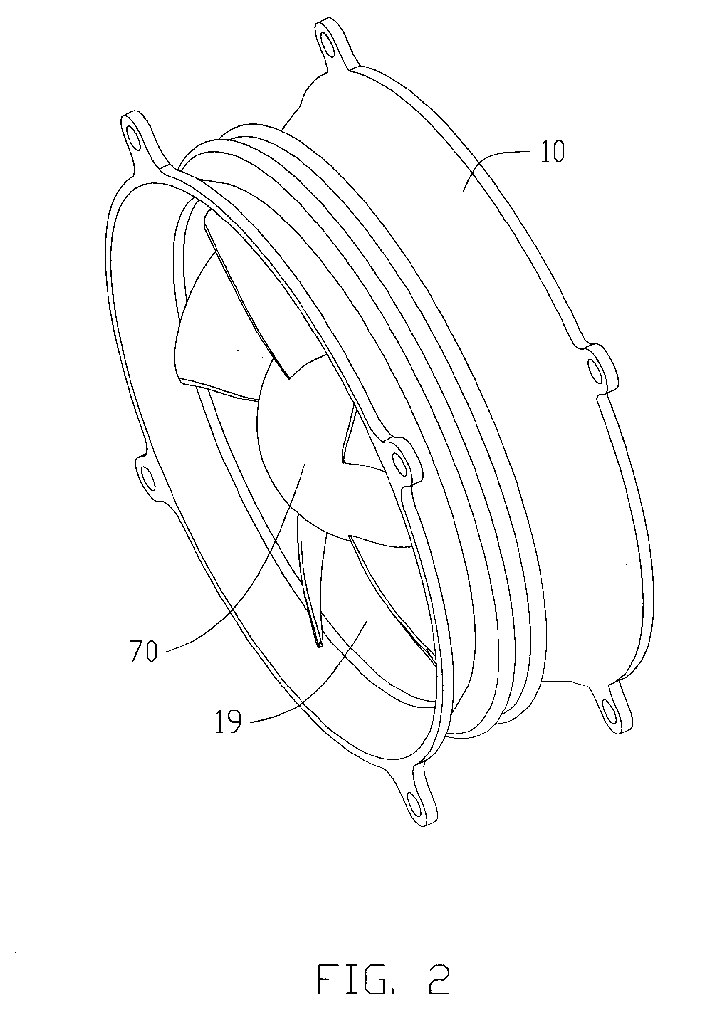
[0025] Also the stator core and the hub can be formed in other shapes if each of which has a profile with a small diameter at the front end thereof adjacent to the air inlet 19 of the electrical fan and a large diameter at the rear end near the air outlet 17 of the electrical fan. Such design not only reduces the flowing resistance of the airflow, but also decreases the volume of the hub and finally improves the amount of airflow. To form the stator core of the present invention, which has a complex configuration t...


PUM


Abstract

A electrical fan includes a frame (10) having a central tube (11), a bearing (30) received in the central tube, a stator (50) mounted around the central tube, and a rotor (70) being rotatably supported by a bearing in the stator. The frame defines an air inlet (19) and an air outlet (17) at two different sides thereof. The stator and the rotor expand radially along a direction from the air inlet to the air outlet. Fan blades (75) extend radially from the rotor. A hub (71) of the rotor has a streamline shaped outer surface. A stator core (511) of the stator is made by powder sintering technology.

Description

CROSS-REFERENCES TO RELATED APPLICATION [0001] This application is related to a co-pending application entitled “FERROMAGNETIC POWDER FOR DUST CORE”, invented by Chao-Nien Tung, Chuen-Shu Hou, Chih-Hao Yang and Lung-Wei Huang, assigned to the same assignee of this application and filed on xxxxxxx with serial number xxxxxxxx. The disclosure of the co-pending application is wholly incorporated herein by reference. FIELD OF THE INVENTION [0002] The present invention relates to an electrical fan, and more particularly to a motor of such an electrical fan. DESCRIPTION OF RELATED ART [0003] With continuing development of the electronic technology, electronic packages such as CPUs (central processing units) are generating more and more heat that is required to be dissipated immediately. Electrical cooling fans are commonly used in combination with heat sinks for cooling the CPUs. [0004] Referring to FIG. 8, a conventional electrical cooling fan includes a stator 6, a rotor 8 rotatable with...

Claims


Application Information

Patent Timeline
Patent Type & Authority Applications(United States)
IPC IPC(8): F03G7/00H02K9/06H02K7/00
CPCF04D29/329H02K7/14F04D25/0646F04D25/064H02K21/12
Inventor TUNG, CHAO-NIENHOU, CHUEN-SHUYANG, CHIH-HAOWU, SHUN-IZHONG, MING
Owner FU ZHUN PRECISION IND SHENZHEN
Why Eureka
Try Eureka