Organic electroluminescent device and method for manufacturing same

a technology of electroluminescent devices and organic materials, applied in the direction of discharge tubes/lamp details, discharge tubes luminescnet screens, electric discharge lamps, etc., can solve the problems of organic material itself deteriorating, the interface between a metal electrode and an organic layer may deteriorate, and the device is extremely sensitive to moisture, so as to prevent the invasion of moisture

Inactive Publication Date: 2007-01-18
SANYO ELECTRIC CO LTD
View PDF15 Cites 79 Cited by
  • Summary
  • Abstract
  • Description
  • Claims
  • Application Information

AI Technical Summary

Benefits of technology

[0048] In the organic electroluminescent apparatus, the outer peripheral surface of the sealing agent is formed in a concave shape, since the sealing agent between the substrate and the sealing plate is subjected to pressure from the outside toward the inside during the fabrication. This allows the sealing agent to be densely formed without the inclusion of foam. This prevents the invasion of moisture to the organic electroluminescent device sufficiently.
[0049] Moreover, the sealing agent is prevented from spreading outside and adhering to terminals that extend outside of the organic electroluminescent device, so that the process of removing the sealing agent adhering on the terminals is omitted.

Problems solved by technology

An organic EL device is extremely sensitive to moisture; specifically, the interface between a metal electrode and an organic layer may deteriorate by the influence of moisture, an electrode may be removed, a metal electrode may be oxidized to increase the resistance, or an organic material itself may deteriorate by the moisture.
Such phenomena lead to a rise in the drive voltage, the generation and growth of dark spots (non-luminescent defects) or reduced luminance, which cause the loss of sufficient reliability.
In that case, the invasion of moisture to the organic EL devices 50 cannot be sufficiently prevented.
The thickness of the sealing can 20J thus increases, which makes thinning of the organic EL apparatus 900 difficult.
However, when a filler such as silica or glass is added to the photo-curing resin layer for lowering the permeability, the viscosity of the photo-curing resin layer increases, and the photo-curing resin layer is whitened.
An increase in the viscosity of the photo-curing resin layer makes it difficult to make the thickness of the photo-curing resin layer uniform while increasing the area of the organic EL device.
For a structure whereby light is extracted outside through an upper surface of the photo-curing rein layer, it is difficult to extract a sufficient amount of light produced from the organic EL layers.
Although in this method, residual foam is prevented by the pressing force of the roller, a shift in the position and a deformation of the cover glass to a saddle shape may occur, which makes it difficult to laminate the cover glass in uniform thickness.

Method used


Image

  • Organic electroluminescent device and method for manufacturing same
  • Organic electroluminescent device and method for manufacturing same
  • Organic electroluminescent device and method for manufacturing same

Examples


first embodiment

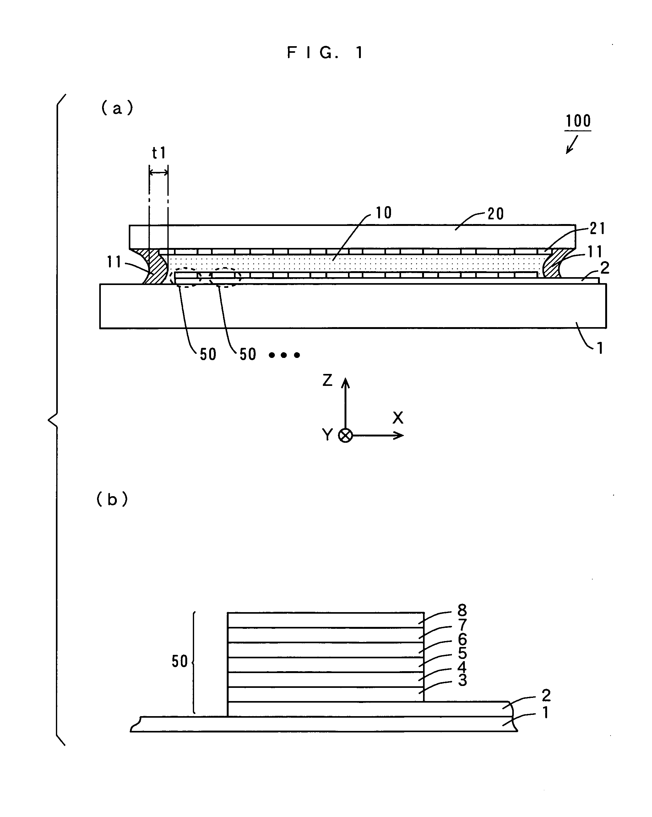
[0068]FIG. 1 (a) is a schematic cross section of an organic EL apparatus according to a first embodiment, and FIG. 1 (b) is a magnified view of a portion of the organic EL apparatus of FIG. 1 (a). The organic EL apparatus 100 in the first embodiment has a top emission structure whereby light is extracted through an upper surface side.

[0069] In the organic EL apparatus 100 of FIG. 1 (a), a plurality of organic EL devices 50 are arranged in matrix form on a substrate 1. Each organic EL device 50 forms a pixel. For a passive matrix type, a glass substrate is used as the substrate 1, and for an active matrix type, a TFT substrate made of a glass substrate having a plurality of TFTs (Thin Film Transistors) and planarization layers thereon is used as the substrate 1.

[0070] Three directions perpendicular to one another are herein defined as X, Y, and Z directions, respectively. The X and Y directions are parallel to a surface of the substrate 1, and the Z direction is vertical to the sur...

second embodiment

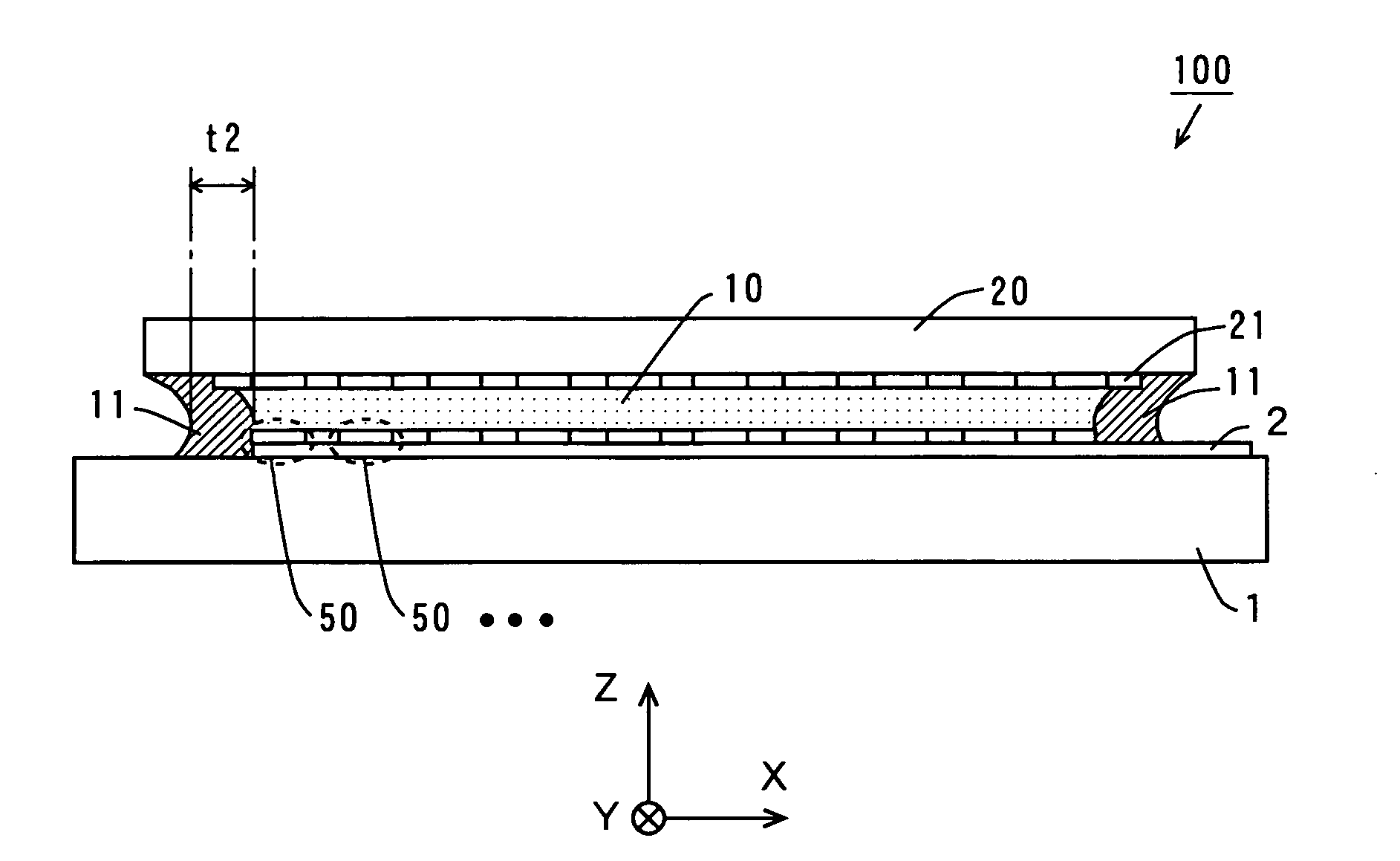
[0101]FIG. 2 is a schematic cross section of an organic EL apparatus according to a second embodiment. The organic EL apparatus 100 in the second embodiment is configured similarly to the organic EL apparatus 100 in the first embodiment, and fabricated by a similar method to that of the first embodiment except the following.

[0102] The width t2 of a sealing agent 11 over the outer peripheral portion on the substrate 1 (the dimension parallel to a surface of the substrate 1) is formed to have a thickness greater than that of the width t1 (about 1 to 5 mm) of the sealing agent 11 in the first embodiment. The width t2 of the sealing agent 11 is about 2 to 10 mm. In this embodiment, the sealing agent 11 is formed so as to surround the plurality of organic EL devices 50. In other words, the outer periphery of the portion on the substrate 1 is covered by the single layer of sealing agent 11, with the sealing agent 11 being in contact with the organic EL devices 50 on the outer periphery. ...

third embodiment

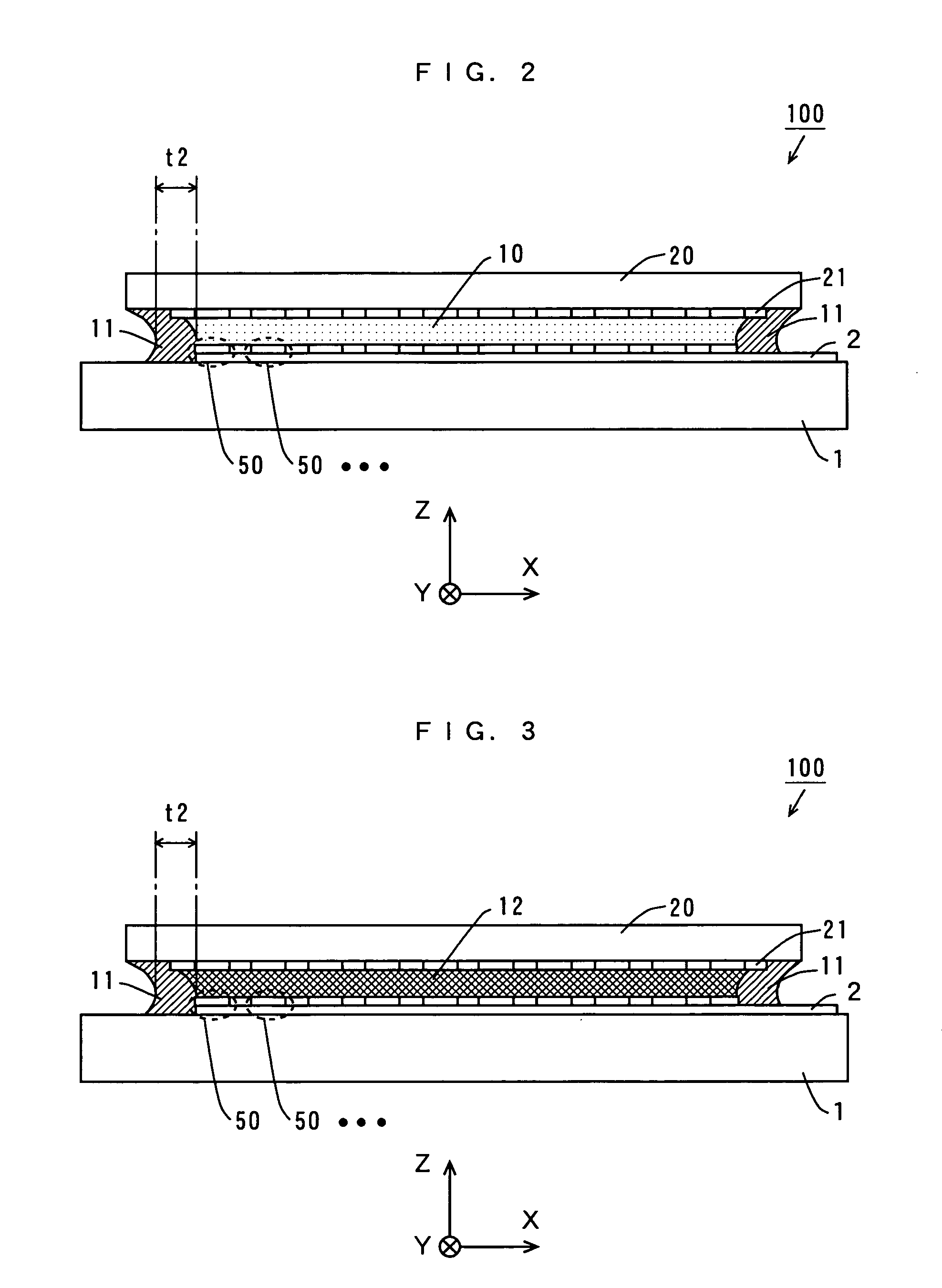
[0103] An organic EL apparatus 100 according to a third embodiment is configured similarly to that of FIG. 2, and fabricated by a similar method to that of the first embodiment except the following.

[0104] A material containing a filler and a desiccant is used for a sealing agent 11 over the outer peripheral portion on the substrate 1. The desiccant added to the sealing agent 11 includes chemical absorbents such as calcium oxide, calcium sulfate, calcium chloride, barium oxide, and strontium oxide or physical absorbents such as activated carbon, silica gel, and zeolite. A material mentioned in the first embodiment is used for the sealing agent 11.

[0105] The addition of a desiccant to the sealing agent 11 allows the absorption of moisture contained in the sealing agent 11. This prevents the invasion of moisture to organic EL devices 50 still more sufficiently.


PUM


Abstract

A plurality of organic EL devices are formed first on a substrate. Next, a film of a sealing agent is formed over the outer periphery of a lower surface (color filter side) of a sealing plate. Then, a sealing agent is dropped onto a central portion of the sealing plate. After that, the sealing plate and the substrate are laminated at a predetermined pressure in a vacuum chamber in a vacuum, and then the vacuum chamber is released from its vacuum state. The substrate and the sealing plate are removed from the vacuum chamber, and the sealing agents between the substrate and the sealing plate are cured by the curing methods suitable for the respective materials.

Description

TECHNICAL FIELD [0001] The present invention relates to organic electroluminescent apparatuses including organic electroluminescent devices and methods of fabricating the organic electroluminescent apparatuses. BACKGROUND ART [0002] The recent diversification of information equipment has led to a growing need for flat panel display devices that require less power consumption than generally used CRTs (Cathode Ray Tubes). As one of such flat panel display devices, organic electroluminescent (hereinafter abbreviated to organic EL) devices having such features as high efficiency, small thickness, lightweight, and low viewing angle dependency are attracting attention. Displays using such organic EL devices are actively being developed. [0003] Organic EL devices are self-emitting devices. In an organic EL device, electrons are injected into the luminescent region from an electron injection electrode, and holes are injected into the luminescent region from a hole injection electrode. The i...

Claims


Application Information

Patent Timeline
Patent Type & Authority Applications(United States)
IPC IPC(8): H01J1/62H01J63/04H01L51/50H01L51/52H05B33/04H05B33/10H05B33/14
CPCH01L51/5237H05B33/14H05B33/10H05B33/04H10K50/846H10K50/8426
Inventor INOUE, HIROTADAHAKU, HISAOHARADA, GAKU
Owner SANYO ELECTRIC CO LTD
Why Eureka
Try Eureka