Bearing device for wheel

a bearing device and wheel technology, applied in the direction of forging presses, instruments, force/torque/work measurement apparatus, etc., can solve the problems of dust and grits entering the bearing, the equipment for the preload control tends to become bulky, and the complication of assembly work, so as to prevent the variation of preload

Inactive Publication Date: 2007-01-18
NTN CORP
View PDF15 Cites 17 Cited by
  • Summary
  • Abstract
  • Description
  • Claims
  • Application Information

AI Technical Summary

Benefits of technology

[0022] Considering that dimensional measurement of individual component parts involves errors, the amount of preload at the time the inner race is press-fitted onto the hub axle changes considerably as the errors accumulates. Also, the change in amount of preload applied as a result of the orbital forging has a variation. Accordingly, if after the press-fitting, measurement of one of the bearing rigidity, the starting torque and the natural frequency is made and a deviation from the target value is fed back to the amount of orbital forging, it is possible to counterbalance the variation of the amount of preload resulting from the press-fitting, thereby preventing the variation in preload during the press-fitting from being left over to the subsequent process step.

Problems solved by technology

However, since the above described preload application control method is a method, in which while a predetermined rotational torque is continuously applied to the bearing, the application of the preload is interrupted when the number of revolution of the bearing attains a target number of revolution, an equipment for the preload control tends to become bulky where it is applied to a relatively large bearing such as, for example, a bearing device for an automobile wheel.
Also, in order to eliminate influences on the torque control brought about by bearing seals, the bearing seals have to be assembled after the preload has been applied, resulting in complication of the assembling work.
Moreover, since there is no bearing seal during the preload being applied, there is the possibility that dusts and grits may enter in the bearing.

Method used


Image

  • Bearing device for wheel
  • Bearing device for wheel
  • Bearing device for wheel

Examples


first embodiment

[0047] Other structural features are similar to those in the

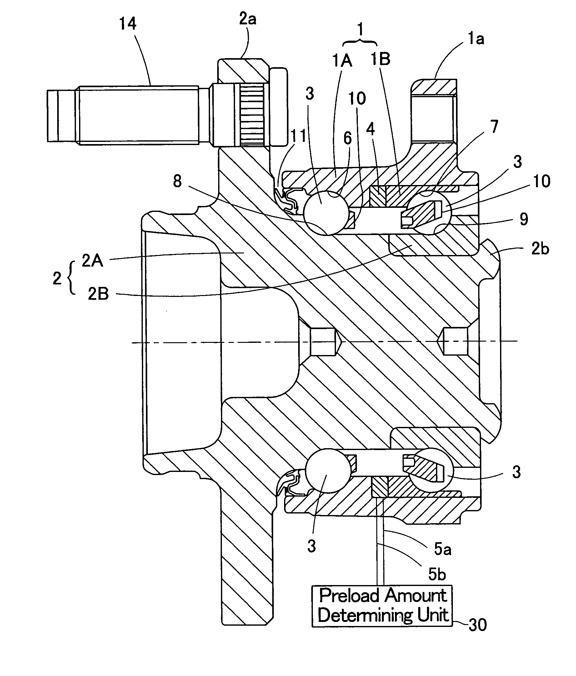
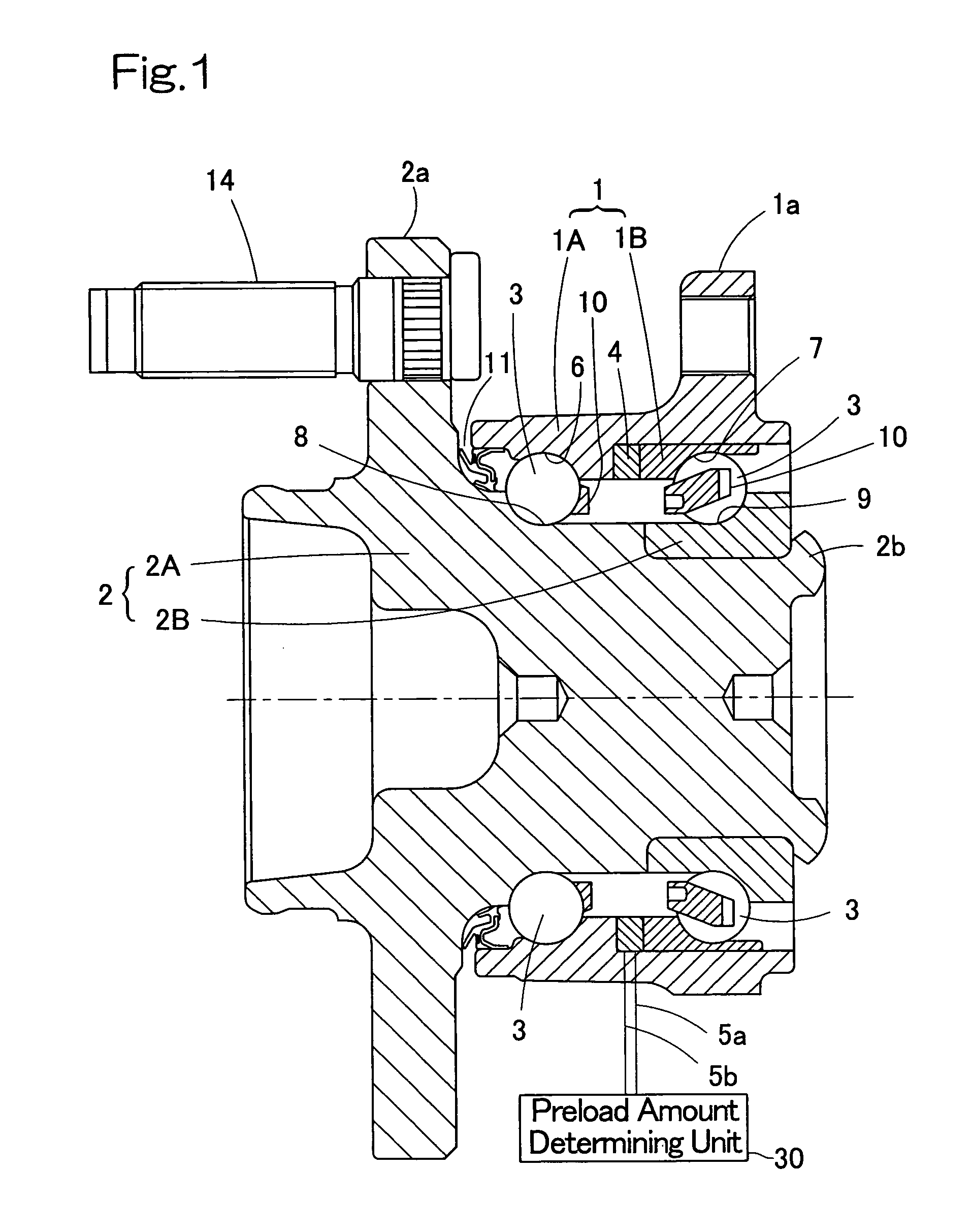
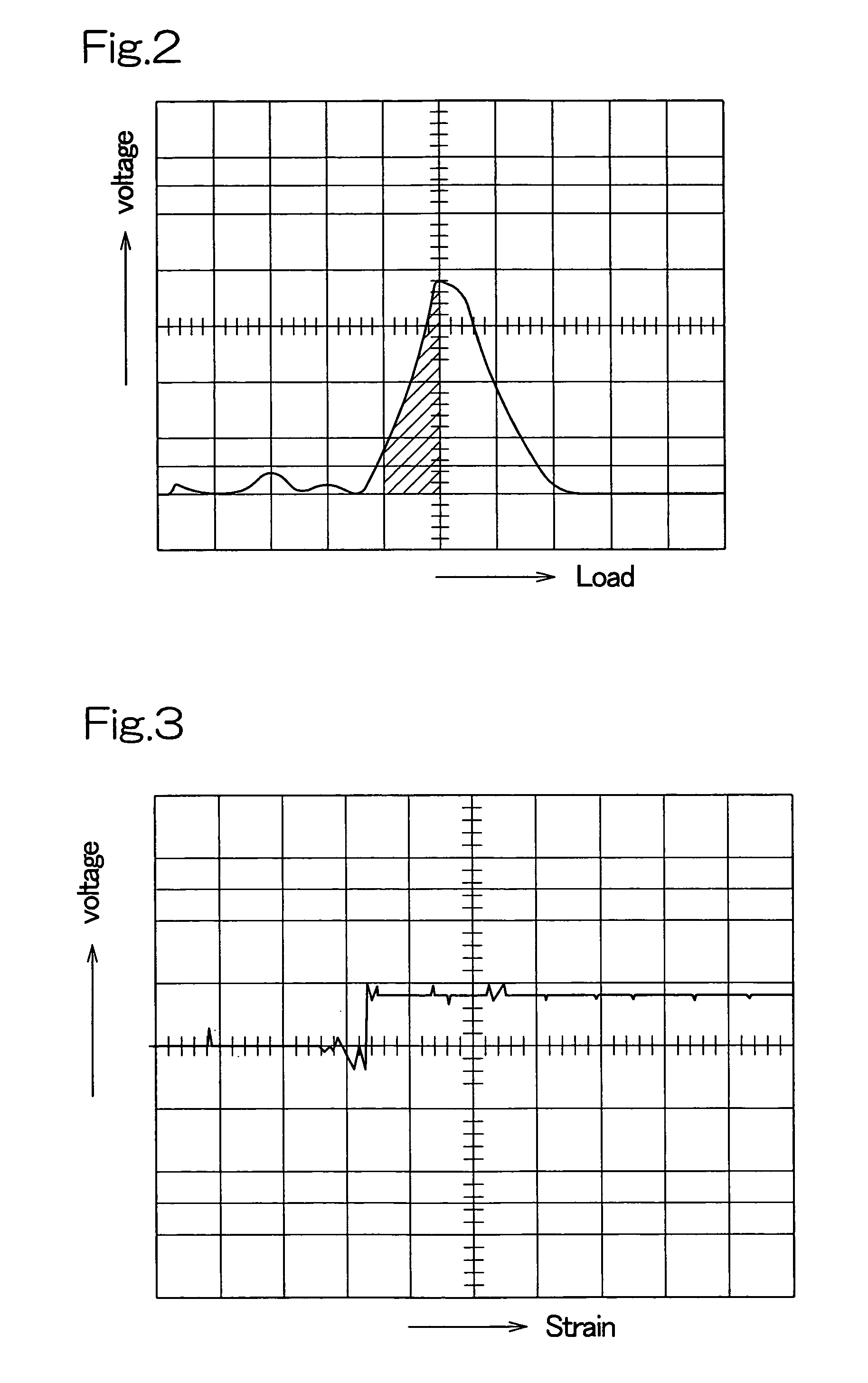
[0048] In the case of this construction, since the crimping work to apply the preload to the bearing is accompanied by change in output voltage of the sensor 4 in the form of the piezoelectric element, the amount of preload of the bearing can be precisely set by controlling this output voltage. Also, since the crimping work to form the crimped portion 2b concurrently serves as the work to apply the preload, no extra work other than the assemblage of the bearing is required solely for the application of preload, resulting in simplification of the work. Even in the case where the strain gauge is used for the sensor 4, the amount of preload can be precisely set in a manner similar to that described above.

[0049]FIG. 5 illustrates a third preferred embodiment of the present invention. This embodiment is such that in the second embodiment shown in FIG. 4, a spacer 12 is interposed between the sensor 4 and the crimped portion 2b ...

sixth embodiment

[0053] Although in any one of the foregoing embodiments the examples have been described, in which as the sensor 4 for detecting the amount of preload the piezoelectric element or the strain gauge is employed, any other element may be employed, provided that it can detect the load. By way of example, a magnetostrictive element may be employed as the sensor 4. This example is shown in FIG. 8. In this example, the sensor 4 is in the form of a ring-shaped detector 4b made up of a ring-shaped magnetostrictive material 4a, a yoke 4ba and a coil 4bb, with the magnetostrictive material 4a interposed between the inner race 2B and the crimped portion 2b. The detector 4b is fitted to one end of the inner race 2B. If during the crimping, the magnetostrictive material 4a, of which magnetic permeability changes with the preload, is taken as a target and detection is then made with the detector 4b having the coil 4bb referred to above, the preload can be controlled.

[0054] Also, in any one of the ...


PUM

PropertyMeasurementUnit
hoop stressaaaaaaaaaa
magnetostrictiveaaaaaaaaaa
magnetoresistanceaaaaaaaaaa

Abstract

To provide a bearing device for a wheel, in which a preload control is easy and a uniform amount of preload can be applied with a bearing seal being mounted, the bearing device for the wheel includes an outer member, an inner member and double rows of rolling elements interposed between the outer member and the inner member. The outer member has a flange on an outer periphery thereof and also has an inner periphery formed with two rolling surfaces. The inner member is formed with rolling surfaces opposed to the rolling surfaces of the outer member. The double rows of the rolling elements are interposed between the rolling surfaces of the outer member and the inner member. A sensor for detecting the amount of preload of the bearing is provided in one of the outer and inner members.

Description

BACKGROUND OF THE INVENTION [0001] 1. Field of the Invention [0002] The present invention relates to a bearing device for a wheel, which is used in an automotive vehicle and is preloaded. [0003] 2. Description of the Prior Art [0004] The bearing device for the wheel is rendered to be a double row rolling bearing in the form of an angular contact ball bearing or a tapered roller bearing and is applied a preload. As a method of controlling the application of a preload in the standard double row rolling bearing of a kind used in a spindle motor or a disc drive device for an information processing equipment, the method is known in which the preload control is carried out with a revolution torque. (See, for example, the Japanese Laid-open Patent Publication No. 2003-74548 published Mar. 12, 2003.) [0005] However, since the above described preload application control method is a method, in which while a predetermined rotational torque is continuously applied to the bearing, the applicatio...

Claims


Application Information

Patent Timeline
Patent Type & Authority Applications(United States)
IPC IPC(8): F16C41/04F16C13/00F16C32/00
CPCB60B27/0005B60B27/0068B60B27/0084F16C43/04F16C19/186F16C19/52B60B27/0094B21J9/025B21K25/00F16C19/185F16C19/522F16C2229/00F16C2326/02
Inventor IWAMOTO, KENICHIOZAKI, TAKAYOSHIKOIKE, TAKASHI
Owner NTN CORP
Why Eureka
Try Eureka