High phosphorous poisoning resistant catalysts for treating automobile exhaust

a technology of high phosphorous and catalysts, which is applied in the direction of physical/chemical process catalysts, separation processes, lighting and heating apparatus, etc., can solve the problems of limiting the durability of catalysts, requiring further increase of catalyst levels, and affecting the effect of catalyst durability

Active Publication Date: 2007-01-18
BASF CATALYSTS LLC
View PDF12 Cites 74 Cited by
  • Summary
  • Abstract
  • Description
  • Claims
  • Application Information

AI Technical Summary

Benefits of technology

[0026] The present invention provides for novel poisoning-resistant catalysts used for automobile exhaust treatment. To alleviate the detrimental affects of engine oil and / or fuel additive poisoning that occurs predominantly at the front end of the catalyst, in the catalysts of this invention, catalytic materials, in particular, high cost precious metal components, are not washcoated onto a front end poison capture zone of the catalyst support structure. The poison capture zone is the inlet or at least upstream 0.5 centimeter of the catalytic substrate. Therefore, phosphorous as well as other poisoning deposits, which tend to accumulate in the poison capture zone on the extreme upstream end of the catalyst support structure, do not block or deactivate any catalytic materials.

Problems solved by technology

This maintenance of operation requirement over extended periods has also challenged catalyst development, and has required still further increased catalyst levels.
Numerous reactions can occur during combustion of a hydrocarbon fuel in a variety of temperature and fuel / air stoichiometric environments and the products of such reactions can limit catalyst durability.
Other octane boosters added to non-leaded fuel, such as methylcyclopentadienyl manganese tricarbonyl (MMT), may result in manganese contained in the exhaust gas and which in excess amount, may coat, foul, or otherwise poison the catalytic layers.
Thus, numerous trace elements still come into contact with the automotive exhaust catalysts, some unavoidably so, and several of these are known to decrease catalyst durability.
Such catalytic poisoning is one of the primary obstacles to the durability of low emission catalyst systems.
However, as the engine burns oil, zinc and phosphorus are exhausted through the catalytic converter, which may accelerate degradation of exhaust catalyst activity.
Although the antiwear additives could be removed from the oil, long-term durability of the engine could suffer.
Although engines are designed to minimize the quantity of engine oil exiting the engine via the combustion chamber and exhaust system, it is inevitable that a small fraction of engine oil is released by this mechanism.
The ZDDP additive of engine oil deleteriously affects catalytic converters due to phosphorus from the ZDDP interfering with active sites within the catalyst.
This poisoning mechanism is quite complex, and highly dependent upon the operating temperature, the oil consumption of the engine, and the source of the oil consumption.
This will result in certain types of phosphorus and / or zinc compounds (among other contaminants).
On the other hand, oil that leaks past the exhaust valve guide and stem, may not go through the combustion process, and result in a different type of poisoning of the catalytic converter, namely, forming a glaze layer covering the catalytic layers.
However, the ZDDP alternatives are cost prohibitive.
Engine oils may be formulated with a lesser amount of ZDDP with the consequences that engine wear and oil oxidation increase, the former limiting engine life and the latter reducing useful oil life.
SOx is a particular problem inasmuch as it is generated by the oxidation of sulfur compound impurities often found in gasoline and diesel fuel.
However, difficulties are encountered when the guard or filter becomes saturated with SOx and / or POx.
However, such systems are inefficient in the degree of protection achieved, may become rapidly fouled, and may remove desirable antioxidant from the oil.

Method used


Image

  • High phosphorous poisoning resistant catalysts for treating automobile exhaust
  • High phosphorous poisoning resistant catalysts for treating automobile exhaust

Examples


example

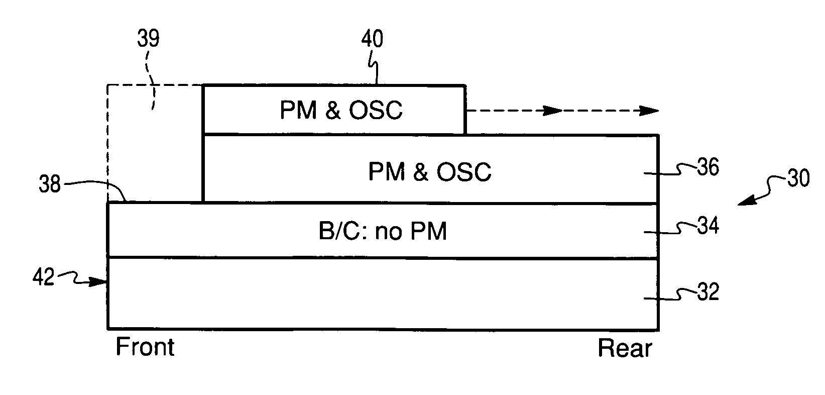
[0046] In this example, a catalyst like that shown in FIG. 1 is formed.

[0047] A first poison capture layer was formed on a ceramic honeycomb. 92.8 parts of gamma-alumina was combined with 7.3 parts of alumina-based binder, 2.9 parts of zirconia based binder, 562 parts DI-water, and 70 parts of 90% concentrated acetic acid to make a slurry of 40% solids content before proceeding to milling. Milling was conducted until the particle size distribution showed that 90% of particles became less than 10 microns.

[0048] After milling, the slurry was coated onto a ceramic honeycomb with 900 cells per square inch (cpsi) and with a wall thickness of 2.5 mils. The coating was performed by dipping the honeycomb substrate into the slurry, draining the slurry, and subsequently by blowing off the excessive slurry with compressed air. The coated honeycomb was dried at 110° C. for 4 hrs. and calcined at 550° C. for 2 hrs.

[0049] A middle layer was then formed by the following procedure. In a planetar...


PUM

PropertyMeasurementUnit
lengthaaaaaaaaaa
concentrationaaaaaaaaaa
temperaturesaaaaaaaaaa

Abstract

The present invention discloses novel catalysts for treating automobile exhaust that have increased resistance to poisoning from oil- and / or fuel-derived additives. In the catalysts of this invention, the catalytic materials are not coated onto a front-end poison capture zone of the support that carries the catalytic layers. Since poisonous elements tend to deposit on the upstream end of the catalyst, such poisons do not inactivate any of the catalytic materials.

Description

FIELD OF THE INVENTION [0001] The present invention relates generally to a system for minimizing the deleterious impact of oil-derived and / or gasoline additive compounds on automotive exhaust aftertreatment systems. BACKGROUND OF THE INVENTION [0002] Automotive emissions control is a mature industry. Automakers and suppliers have been challenged to control and reduce vehicle tailpipe emissions by the U.S. Clean Air Act in 1965 and subsequent legislation in other countries. Base engine emissions of controlled exhaust products have been reduced significantly over the past thirty years, as compliance with periodically decreasing tailpipe limits has been made possible through the use of catalytic converters. [0003] A catalytic converter typically contains one or more catalytic elements, which lower hydrocarbons (HC), carbon monoxide (CO) and / or nitrogen oxides (NOx). Some catalyst systems are also designed to reduce particulate matter from diesel engines. [0004] The individual catalysts...

Claims


Application Information

Patent Timeline
Patent Type & Authority Applications(United States)
IPC IPC(8): B01D50/00
CPCB01D53/945B01J23/63B01J35/0006B01J35/04B01J37/0244Y02T10/22F01N3/0828F01N3/085F01N2370/02F01N2510/06F01N2510/0682F01N3/0814B01D2255/1023B01D2255/1025B01D2255/204B01D2255/9025B01D2258/014Y02A50/20B01J23/38B01D53/34F01N3/10Y02T10/12
Inventor FRANKLIN CHEN, SHAU-LIN
Owner BASF CATALYSTS LLC
Why Eureka
Try Eureka