Method of reducing rigidity of angioplasty balloon sections

Inactive Publication Date: 2007-01-18
ABBOTT LAB INC
View PDF16 Cites 39 Cited by
  • Summary
  • Abstract
  • Description
  • Claims
  • Application Information

AI Technical Summary

Benefits of technology

[0021] In one embodiment, the wall thickness of the tapered portion having undergone the ablative process is substantially equal to the nominal wall thickness of the medial working section of the balloon. Alternatively the tapered sections may have thicknesses greater or less than the nominal wall thickness of the balloon. In either event, the indentations are configured to increase balloon maneuverability and pliability by reducing balloon wall stiffness near the mounting sections, and allows a tighter wrapping of the balloon for a reduced deliv

Problems solved by technology

Thicker walls near the stems reduce maneuverability of the balloon and catheter.
The dilatation balloon cannot be as tightly wrapped, meaning its delivery profile is larger, limiting the capacity

Method used


Image

  • Method of reducing rigidity of angioplasty balloon sections
  • Method of reducing rigidity of angioplasty balloon sections
  • Method of reducing rigidity of angioplasty balloon sections

Examples


Embodiment Construction

[0038] While the present invention will be described with reference to a few specific embodiments, the description is illustrative of the invention and is not to be construed as limiting the invention. Various modifications to the present invention can be made to the preferred embodiments by those skilled in the art without departing from the true spirit and scope of the invention as defined by the appended claims. It will be noted here that for a better understanding, like components are designated by like reference numerals throughout the various figures.

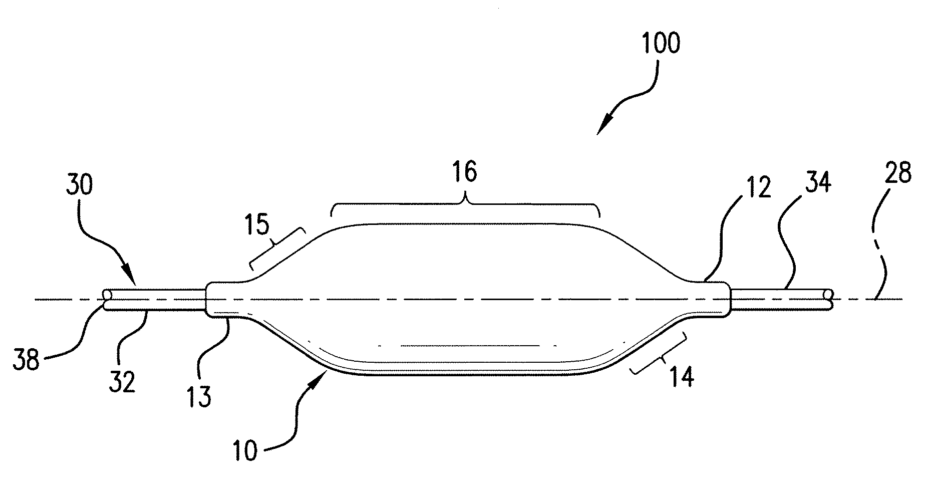
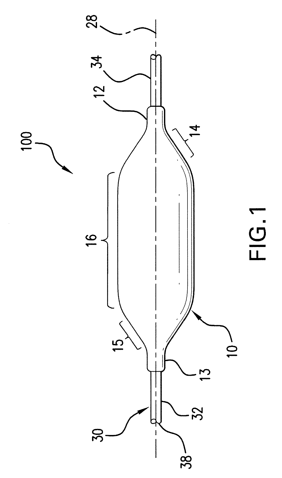
[0039] In one aspect of the present invention, a medical device is provided. The medical device generally comprises an elongated shaft member having a proximal end and a distal end. The elongated shaft member further includes a guidewire lumen and an inflation lumen extending along a length thereof. Further, an expandable member such as a balloon is disposed proximate the distal end of the shaft. The expandable member is in fluid...


PUM

PropertyMeasurementUnit
Lengthaaaaaaaaaa
Thicknessaaaaaaaaaa
Flexibilityaaaaaaaaaa

Abstract

A dilatation balloon is fabricated according to a process that forms cavities and indentations in the balloon and/or catheter sections. A length of tubing is axially elongated and radially expanded in a form to provide the requisite biaxial orientation and strength. Then, an excimer laser or another type of laser or mechanical material removal tool is used to remove the polymeric material, virtually without thermal effects. Cavities in the sleeve sections of the balloon are defined and if desired, indentations in the cone sections are defined. Material removal, particularly near the balloon sleeves enables a thinner, more flexible bonding area between the catheter shaft and the balloon. Further, the indentations along the cone sections enables tighter wrapping of the balloon for a reduced delivery profile. Rigidity near the sleeves is reduced for better maneuverability of the catheter in tortuous passageways.

Description

CROSS-REFERENCE TO RELATED APPLICATION [0001] This application claims the benefit of U.S. Provisional Patent Application Ser. No. 60 / 692,920, filed Jun. 17, 2005, the entire content of which is incorporated herein by reference thereto.FIELD OF THE INVENTION [0002] The present invention relates generally to dilatation balloon catheters and systems used for expansion against an obstruction within a body vessel or channel, or to deliver devices such as, but not limited to, intravascular stents and therapeutic agents to sites within vascular or tubular channel systems of the body. Particularly, the invention relates to a dilatation balloon catheter and system having an improved dilatation balloon. The dilatation balloon has improved pliability, trackability and maneuverability in the passages of the vascular system. BACKGROUND OF THE INVENTION [0003] The present invention relates to dilatation balloon catheters employed in applications such as percutaneous transluminal angioplasty (PTA)...

Claims


Application Information

Patent Timeline
IPC IPC(8): A61M29/00A61F2/958
CPCA61M25/1034A61M25/1038A61M25/104A61M2025/1004A61M2025/1031Y10T156/1062A61M2025/1093B23K26/4065B29C59/165B29C2791/009B29L2031/7542A61M2025/1086B23K2103/42B23K2103/50
Inventor WARNACK, BORISHARTWIG, JUDITHPSCHIBL, SILKEYRIBARREN, TRAVIS RICHARDOEPEN, RANDOLF VONRIETH, THOMASCOFFEY, LORCANZUCKER, ARIK
Owner ABBOTT LAB INC
Why Eureka
Try Eureka