
Method and device for sensorless vector control for ac motor

a vector controller and ac motor technology, applied in the direction of motor/generator/converter stopper, dynamo-electric gear control, motor/generator/converter stopper, etc., can solve the problem of inability to operate in a stable way, inability to accurately estimate the speed, and inability to effectively control the speed. the effect of accuracy and accuracy

Inactive Publication Date: 2007-01-25
YASKAWA DENKI KK
View PDF5 Cites 25 Cited by
  • Summary
  • Abstract
  • Description
  • Claims
  • Application Information

AI Technical Summary

Benefits of technology

[0010] Further, it is a second object of the present invention to provide a vector control method and a vector controller for an a.c. motor without using a speed sensor in which when a speed deviation is large, a quick acceleration can be realized without an unstable control.
[0031] As described above, in the first vector control method and the vector controller for an a.c. motor without using a sensor according to the present invention, since the speed estimated value or the magnetic flux estimated value of the all-dimensional magnetic flux speed observer can be made to correspond to the speed or the magnetic flux of an actual a.c. motor, speed can be accurately estimated even in the a.c. motor that is liable to be magnetically saturated and a speed accuracy or a torque accuracy can be effectively improved.
[0032] Further, in the second vector control method and the vector controller for an a.c. motor without using a sensor according to the present invention, the speed deviation value inputted to the speed control unit is limited from a time during which the a.c. motor can be accelerated in the shortest time and a time during which the speed estimating unit can be accelerated in the shortest time. Accordingly, even when the a.c. motor is abruptly accelerated or decelerated, the speed can be effectively controlled in a stable way.

Problems solved by technology

However, when the induction motor having a small capacity and a small inertia is suddenly accelerated under a state having no load, the speed changes during the very little time (sampling time).
Thus, an unstable control state arises, a large quantity of electric current flows or an operation is carried out under an excessively slipping state, so that the induction motor cannot be operated in a stable way.
Particularly, when an accelerating time is short or the variation of speed is large, the above-described state is liable to arise.
Further, the method described in the Patent Document 2 serves to treat the induction motor having a large capacity in which the rise of the secondary magnetic flux is slow, so that the above-described problem in the induction motor having the small capacity and the small inertia cannot be solved.
In such a way, even when the variation of speed is low, a torque limit undesirably operates.
However, this method is a method for preventing the excessive speed, so that the above-described problem in the induction motor having the small capacity and the small inertia cannot be solved.

Method used


Image

  • Method and device for sensorless vector control for ac motor
  • Method and device for sensorless vector control for ac motor
  • Method and device for sensorless vector control for ac motor

Examples


first embodiment

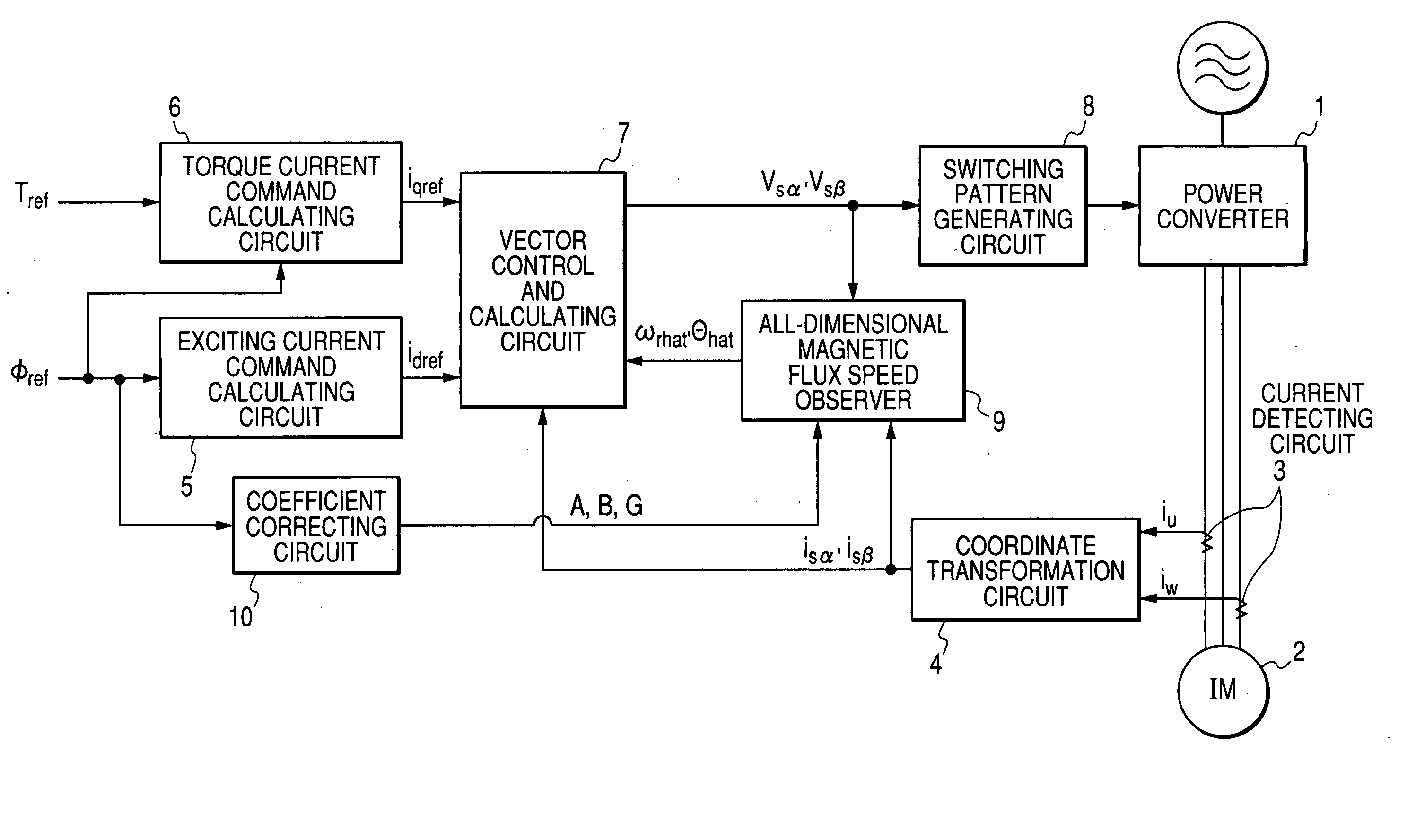
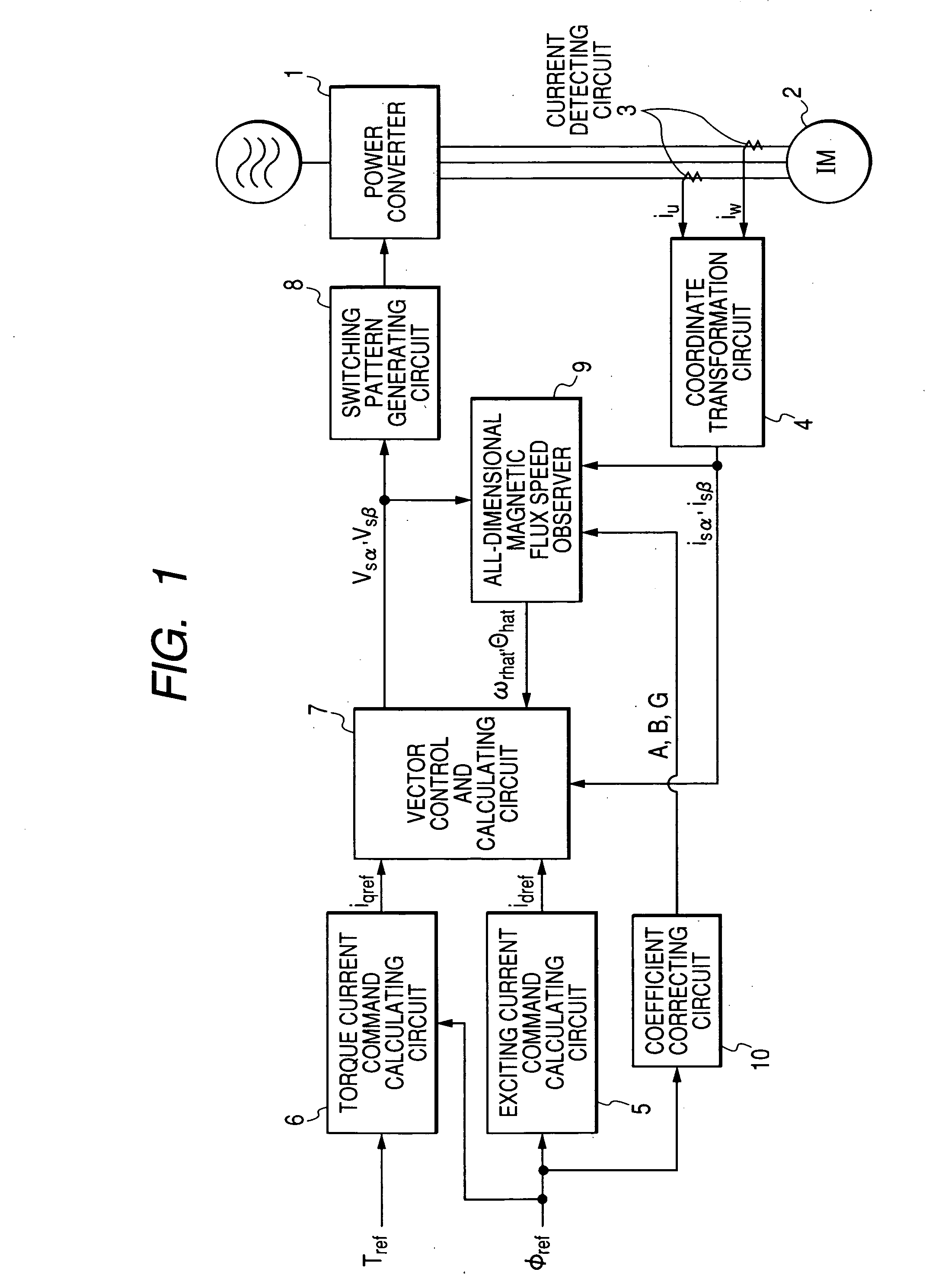
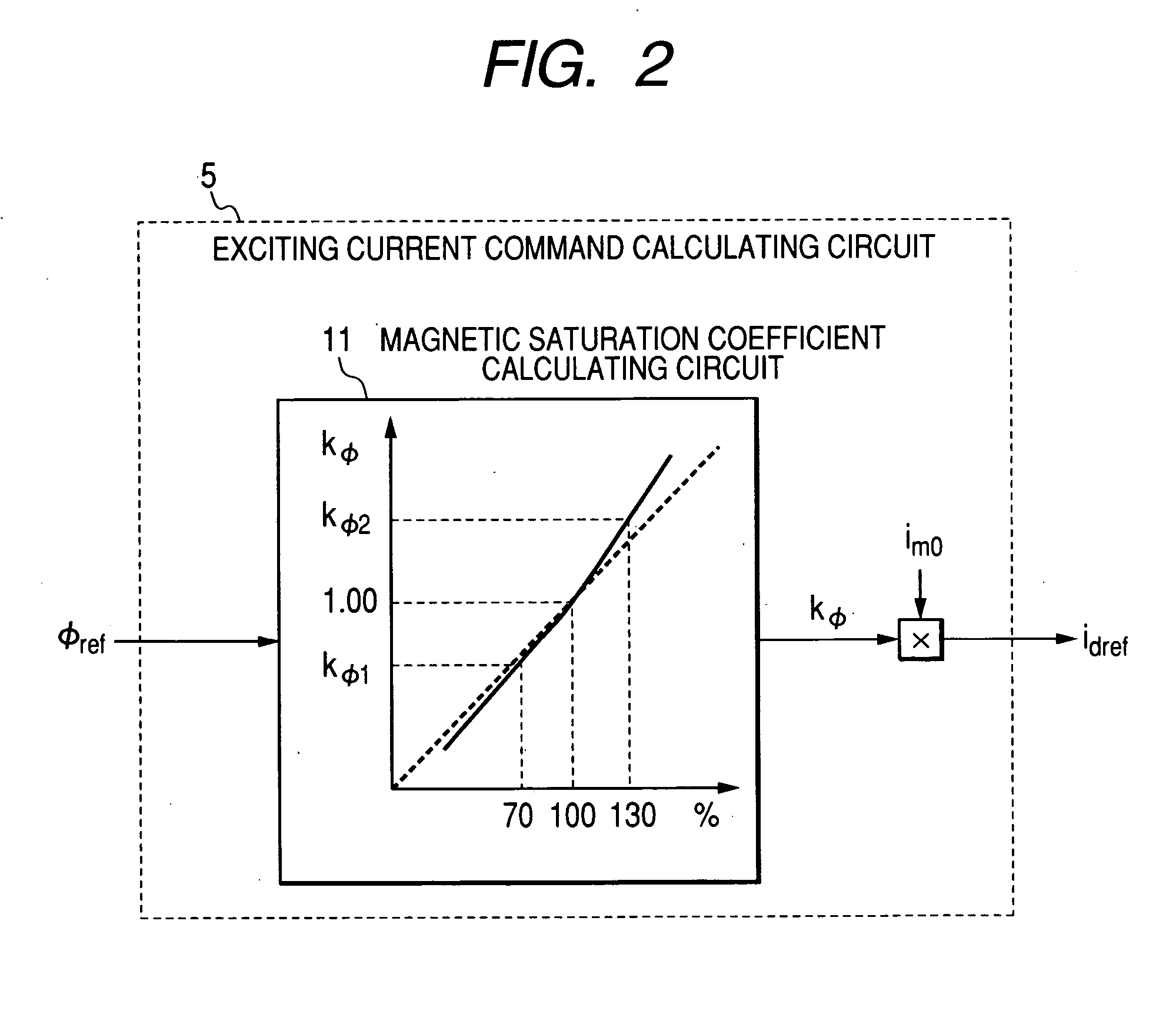
[0041]FIG. 1 is a block diagram showing the structure of a vector controller for an a.c. motor without using a sensor in the present invention. FIG. 2 is a block diagram showing the structure of an exciting current command calculating circuit. FIG. 3 is a block diagram showing the structure of a torque current command calculating circuit.

[0042] The vector controller for an a.c. motor without using a sensor in this embodiment includes a power converter 1 for converting three-phase alternating current to d.c. voltage by a power element, converting the d.c. voltage to an alternating current having an arbitrary frequency and voltage by a PWM control system and outputting the alternating current, an induction motor 2 as one kind of the a.c. motor that is driven by the alternating current outputted from the power converter 1, a current detecting circuit 3 for detecting the current supplied to the induction motor , a coordinate transformation circuit 4 for outputting primary current detect...

third embodiment

[0095]FIG. 5 is a block diagram showing the structure of a vector controller for an a.c. motor without using a sensor according to a

[0096] The vector controller for an a.c. motor without using a sensor in this embodiment includes a power converter 1 for converting three-phase alternating current to d.c. voltage by a power element, converting the d.c. voltage to an alternating current having an arbitrary frequency and voltage by a PWM control system and outputting the alternating current, an induction motor 2 as one kind of the a.c. motor that is driven by the alternating current outputted from the power converter 1, a current detecting circuit 3 for detecting the current supplied to the induction motor , a coordinate transformation circuit 4 for outputting primary current detected values isα, isβ, that are obtained by performing a three-phase to two-phase transformation of the current detected in the current detecting circuit in a stator coordinate system, a speed deviation limit ci...


PUM


Abstract

To provided a control method and a controller for an a.c. motor without using a speed sensor in which the speed estimated value or the magnetic flux estimated value of an all-dimensional magnetic flux speed observer can be made to correspond to that of an actual a.c. motor. A controller for an a.c. motor includes a vector control and calculating circuit (7) for controlling and calculating a vector from an exciting current command calculated in an exciting current command calculating circuit (5), a torque current command calculated in a torque current command calculating circuit (6), a coordinate transformed current detected value obtained in a coordinate transformation circuit (4), a speed estimated value and a magnetic flux phase estimated value and outputting an output voltage command, a switching pattern generating circuit (8) for generating a signal for PWM driving a power converter (1) from the output voltage command and an all-dimensional magnetic flux speed observer (9) for estimating the speed estimated value and the magnetic flux phase estimated value from the output voltage command and the coordinate transformed current detected value. In the controller for the a.c. motor, a coefficient correcting circuit 10 is provided for correcting the coefficient of a determinant used in the all-dimensional magnetic flux speed observer (9) in accordance with a magnetic flux command.

Description

TECHNICAL FIELD [0001] The present invention relates to a vector control method and a vector controller for an a.c. motor, particularly, an induction motor without using a speed sensor. RELATED ART [0002] As a usual speed estimating method for an induction motor and a driving device for an induction motor, for instance, JP-A-Hei08-205599 (Patent Document 1) proposes that a speed estimated value is corrected by the absolute value of a secondary inter-linkage magnetic flux obtained from the estimated value of the secondary inter-linkage magnetic flux to reduce the error of the speed estimated value in an all-dimensional magnetic flux speed observer. [0003] Further, JP-A-2002-136196 (Patent Document 2) proposes that, to suppress a shock due to a phenomenon that an excessively large quantity of torque current flows until a secondary magnetic flux rises, a timer, a limiter setting calculating unit and a torque limiter are inserted into a path from a command value generating unit for gene...

Claims


Application Information

Patent Timeline
IPC IPC(8): H02P27/04H02P21/00H02P21/13H02P21/14H02P21/22H02P23/07H02P23/12H02P23/14H02P27/08
CPCH02P21/0042H02P2207/01H02P21/146H02P21/141H02P21/26H02P21/18
Inventor IURA, HIDEAKIYAMAMOTO, YOICHINAKAMURA, SHIGEKAZU
Owner YASKAWA DENKI KK
Learn More