Hexagonal ferrite magnetic powder, method for producing the same and magnetic recording medium

Active Publication Date: 2007-01-25
FUJIFILM CORP +1
7 Cites 104 Cited by

AI-Extracted Technical Summary

Problems solved by technology

However, the induction type magnetic head is becoming insufficient for use in the presently required reproduction of high-density records.
That is, when the number of coil turns of a reproduction head is increased in order to obtain a larger reproduction output, there results an increased inductanc...

Benefits of technology

[0078] The process of manufacturing the coating composition to be used in the invention for forming the magnetic layer of the magnetic recording medium comprises at least a kneading step, dispersion step, and mixing steps provided as needed before and after these steps. Each of the steps may be divided into two or more stages. All of the starting materials employed in the invention, including the hexagonal ferrite magnetic powder, the non-magnetic powder, the binder, carbon black, the abrasive, the antistatic agent, the lubricant and the solvent may be added at the beginning or during any step. Further, each of the starting materials may be divided and added during two or more steps. For example, polyurethane may be divided and added in the kneading step, dispersing step and mixing step for viscosity adjustment after dispersion. In order to achieve the object of the invention, conventionally known manufacturing techniques may be employed for some of the steps. A kneading device of high kneading strength, such as an open kneader, continuous kneader, pressure kneader or extruder, is preferably used in the kneading step. Details of these kneading treatments are described in JP-A-1-106338 and JP-A-1-79274. Further, glass beads may be employed to disperse the magnetic layer-forming coating composition and the non-magnetic layer-forming coating composition. A dispersion medium having a high specific gravity such as zirconia beads, titania beads or steel beads is suitable for use as the glass beads. The particle size and the packing ratio of the dispersion medium are optimized for use. As a dispersing machine, any known dispersing machine may be used.
[0079] In the method of manufacturing the magnetic recording medium of the invention, the magnetic layer is formed by coating a magnetic layer-forming coating composition on the surface of a running support in a predetermined thickness. Here, a plurality of magnetic layer-forming coating compositions may be sequentially or simultaneously multi-layer coated, and the non-magnetic layer-forming coating composition and the magnetic layer-forming coating composition may be sequentially or simultaneously multi-layer coated. As coating machines suited for use in coating the magnetic layer-forming coating composition and the non-magnetic layer forming coating composition, an air doctor coater, a blade coater, a rod coater, an extrusion coater, an air knife coater, a squeeze coater, an immersion coater, a reverse roll coater, a transfer roll coater, a gravure coater, a kiss coater, a cast coater, a spray coater and a spin coater can be used. As to these coating machines, reference can be made to, for example, Saishin Coating Gijutsu (May 31, 1983), issued by K.K. Sogo Gijutsu Center.
[0080] With a magnetic tape, the layer formed by coating the magnetic layer-forming coating composition is subjected to the orientation treatment in the longitudinal direction by applying a cobalt magnet...

Abstract

A hexagonal ferrite magnetic powder having an average tabular diameter of from 15 to 28 nm, a coercive force (Hc) of from 2,000 to 5,000 Oe (from 160 to 400 kA/m), a switching field distribution (SFD) of from 0.3 to 0.7 and a D70/D50 of from 1.05 to 1.25. This magnetic powder can be obtained by melting and quenching starting materials to obtain an amorphous product, and thermally treating the product, which comprises increasing a temperature at a rate of 300 to 500° C./hr in a temperature range of 550 to 600° C. in the thermal treatment before the temperature reaches the thermally treating temperature.

Application Domain

Technology Topic

Image

  • Hexagonal ferrite magnetic powder, method for producing the same and magnetic recording medium
  • Hexagonal ferrite magnetic powder, method for producing the same and magnetic recording medium

Examples

  • Experimental program(1)

Example

Examples 1 to 8 and Comparative Examples 1 to 9
Preparation of Hexagonal Ferrite Magnetic Powder
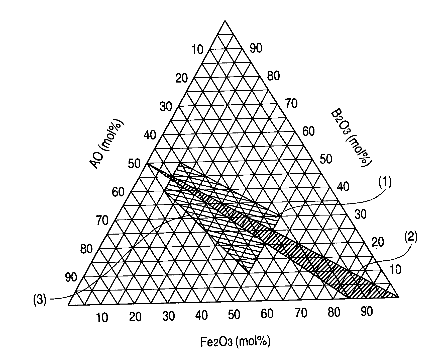
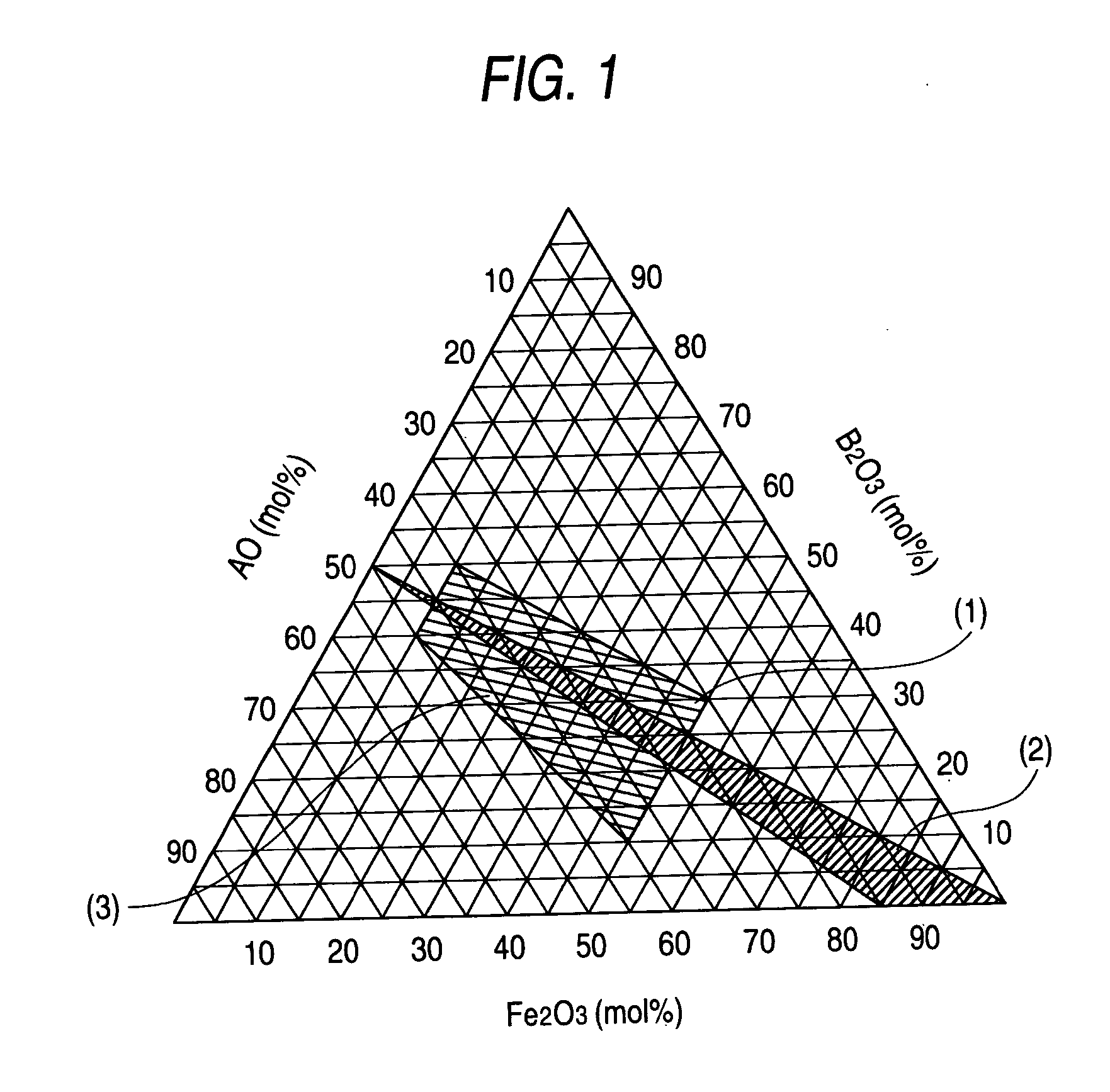
[0093] In order to obtain an amorphous product comprising 31 mol % of BaO, 31 mol % of B2O3 and 38 mol % of a Ba ferrite component represented by the composition formula of BaO.Fe12−3(x+y)/2CoxZnyNb(x+y)/2O18, starting materials corresponding respective elements were weighed and well mixed. The resulting mixture was put in a platinum crucible and molten at a temperature of 1350° C. by means of a high-frequency heating furnace. After melting all of the starting materials, the molten mixture was stirred for 1 hour to homogenize. The thus-homogenized molten product was poured onto a water-cooled twin rollers rotating at a high speed to thereby mill and quench, thus an amorphous product being obtained. The resultant amorphous product was heated from ordinary temperature to 550° C. in 5 hours, then heated at a rate shown in Table 1 in the temperature region ranging from 550° C. to 600° C. to a predetermined crystallization temperature, followed by conducting crystallization for 5 hours to precipitate Ba ferrite crystals. The crystallized product was pulverized for enhancing the efficiency of treatment with an acid, then acid-treated in a 10% acetic acid solution for 4 hours under stirring while controlling the solution temperature at 80° C. or above to thereby dissolve a glass component of BaO—B2O3. After repeatedly conducting washing with water, the slurry was dried to obtain a magnetic powder.
[0094] Characteristic properties of the thus-obtained magnetic powder are shown in Table 1.
[0095] The magnetic characteristics and SFD were measured by means of a vibrating sample magnetometer (VSM) under the condition of 10 KOe in maximum field with making sample-packing density to 1.39 to 1.44 g/cm3.
[0096] The specific surface area was measured according to the BET single-point method under degassing conditions of 350° C. and 15 minutes.
[0097] As to the average tabular diameter, a powder sample was photographed at an arbitrarily selected position under a transmission electron microscope (300,000 to 500,000×), and 300 particles whose side was photographed were arbitrarily selected, followed by measuring their sizes.
[0098] As to D50 and D70, the particle size is plotted as abscissa, and the cumulative number of particles belonging to a given section is plotted as ordinate on a logarithmic probability paper, with D50 and D70 being read from the cumulative number of particles % for each section. TABLE 1 (A) Temperature- Average Crystallization increasing Particle Temperature rate Size Example x y ° C. ° C./hr nm Example 1 0.1 0.35 660 300 22 Example 2 0.1 0.3 660 300 21 Example 3 0.1 0.25 660 300 22 Comparative 0.1 0.35 660 100 20 Example 1 Comparative 0.1 0.3 660 100 19 Example 2 Comparative 0.1 0.25 660 100 20 Example 3 Comparative 0.1 0.35 800 700 42 Example 4 Example 4 0.1 0.3 660 450 26 Comparative 0.1 0.35 750 550 35 Example 5 Comparative 0.1 0.35 660 250 22 Example 6 Comparative 0.1 0.35 600 300 13 Example 7 Example 5 0.1 0.1 640 300 18 Example 6 0.1 0.4 720 300 26 Comparative 0.1 0.35 770 300 30 Example 8 Comparative 0.1 0.6 710 300 23 Example 9 Example 7 0.1 0.1 710 300 24 Example 8 0.1 0 710 300 24 (B) Specific Surface D70/ Hc σs Area Example D50 Oe kA/m SFD A · m2/kg m2/g Example 1 1.13 2230 178 0.6 53 61 Example 2 1.15 2470 198 0.55 53 62 Example 3 1.2 2670 214 0.53 52 64 Comparative 1.26 1970 158 0.88 53 64 Example 1 Comparative 1.27 2330 186 0.75 50 63 Example 2 Comparative 1.29 2500 200 0.71 50 66 Example 3 Comparative 1.3 2690 215 0.55 58 40 Example 4 Example 4 1.21 2300 184 0.5 53 62 Comparative 1.29 2500 200 0.6 56 47 Example 5 Comparative 1.27 2100 168 0.77 52 64 Example 6 Comparative 1.24 860 69 4.4 37 86 Example 7 Example 5 1.16 3000 240 0.6 47 74 Example 6 1.14 2450 196 0.42 55 49 Comparative 1.23 3100 248 0.45 58 43 Example 8 Comparative 1.17 1900 152 0.8 51 54 Example 9 Example 7 1.18 3500 280 0.39 50 52 Example 8 1.18 4000 320 0.35 50 52
Preparation of a Coating Composition for Tape
[0099] Coating Composition for Forming a Magnetic Layer Barium ferrite magnetic powder 100 parts Polyurethane resin 12 parts weight-average molecular weight: 10,000 sulfonic acid functional group: 0.5 meq/g α-Alumina 8 parts HIT60 (manufactured by Sumitomo Chemical) Carbon black (particle size: 0.015 μm) 0.5 part #55 (manufactured by Asahi Carbon) Stearic acid 0.5 part Butyl stearate 2 parts Methyl ethyl ketone 180 parts Cyclohexanone 100 parts
[0100] Coating Composition for Forming a Non-Magnetic Layer Non-magnetic powder, α-iron oxide 100 parts Average major axis length: 0.09 μm; Specific surface area by the BET method: 50 m2/g pH: 7 DBP oil absorption capacity: 27 to 38 ml/100 g Surface treatment layer Al2O3: 8% by weight Carbon black Conductex SC-U (manufactured by 25 parts Colombian Carbon Co.) Vinyl chloride copolymer MR104 (manufactured by 13 parts Nippon Zeon Co., Ltd.) Polyurethane resin UR8200 (manufactured by 5 parts Toyobo Co., Ltd.) Phenylphosphonic acid 3.5 parts Butyl stearate 1 part Stearic acid 2 parts Methyl ethyl ketone 205 parts Cyclohexanone 135 parts
[0101] MR104 (manufactured by Nippon Zeon Co., Ltd.)
Method for Preparing a Magnetic Tape
[0102] Individual components for each coating composition were kneaded in a kneader. Each of the resulting coating compositions was introduced into a horizontal sand mill retaining 1.0-mmφ zirconia beads in an amount of 65% based on the volume of the dispersing zone thereof using a pump, and dispersed for 120 minutes (time during which the composition substantially stayed in the dispersing zone) at 2,000 rpm. To the resulting dispersion of the non-magnetic layer-forming coating composition was added 5.0 parts of polyisocyanate, and to the resulting dispersion of the magnetic layer-forming coating composition was added 2.5 parts of the polyisocyanate. Further, 3 parts of methyl ethyl ketone was added to each coating composition, and each of the resulting coating compositions was filtered through a filter of 1 μm in average pore size. Thus, there were prepared a coating composition for forming a non-magnetic layer and a coating composition for forming a magnetic layer.
[0103] The thus-obtained coating composition for forming the non-magnetic layer was coated on a 4 μm thick polyethylene terephthalate base in a dry thickness of 1.5 μm and, after drying, the coating composition for forming the magnetic layer was successively multi-layer coated in a thickness of the magnetic layer of 0.10 μm and, while the magnetic layer was still in a wet state, the orientation was performed by means of a cobalt magnet having a magnetic force of 6,000 G (600 mT) and a solenoid having a magnetic force of 6,000 G, followed by drying. Subsequently, calendering was conducted using a 7-stage calender at a temperature of 90° C. and a linear pressure of 300 kg/cm (294 kN/m). Then, a 0.5-μm thick backcoat layer (prepared by dispersing 100 parts of carbon black of 17 nm in average particle size, 80 parts of calcium carbonate of 40 nm in average particle size and 5 parts of α-alumina of 200 nm in average particle size were dispersed in nitrocellulose resin, polyurethane resin and polyisocyanate) was coated. The resulting web-shaped magnetic recording medium was slit into 3.8 mm-wide product. The slit product was then subjected to surface-cleaning treatment by means of a tape-cleaning device provided in an apparatus having a tape delivery mechanism and a tape wind-up mechanism, wherein non-woven fabric and a razor blade are provided so as to be pressed against the magnetic surface. Thus, a magnetic tape medium was obtained.
[0104] Magnetic characteristics of the thus-obtained magnetic tapes were examined as described above. Also, output and noise were checked. These were measured by fitting a recording head (MIG; gap: 0.15 μm; 1.8 T) and an AMR head for reproduction to a drum tester. The head-medium relative speed was adjusted to 15 m/sec, and noise was measured in terms of modulated noise. SN was given with SN in Comparative Example 4 as 0 dB.
[0105] The results are shown in Table 2. Additionally, in Table 2, numbers of Examples and Comparative Examples correspond to the numbers of Examples and Comparative Examples of magnetic powders shown in Table 1. TABLE 2 Hc Bm Output Noise S/N Example Oe kA/m SQ SFD mT dB dB dB Example 1 2380 190.4 0.62 0.4 149 −1.8 −4.2 2.4 Example 2 2630 210.4 0.6 0.38 148 −1.3 −4.3 3.1 Example 3 2830 226.4 0.62 0.37 147 −1.1 −4.1 3.0 Comparative Example 1 2100 168 0.58 0.54 148 −3.4 −4.7 1.3 Comparative Example 2 2480 198.4 0.56 0.48 140 −3.3 −4.2 0.9 Comparative Example 3 2660 212.8 0.58 0.46 139 −2.9 −4.4 1.5 Comparative Example 4 2850 228 1.02 0.38 164 0.0 0.0 0.0 Example 4 2450 196 0.7 0.35 151 −1.2 −3.3 2.2 Comparative Example 5 2660 212.8 0.88 0.4 159 −0.9 −1.5 0.6 Comparative Example 6 2240 179.2 0.62 0.49 147 −2.9 −4.3 1.4 Comparative Example 7 890 71.2 0.44 2.3 105 −9.8 −4.3 −5.5 Example 5 3170 253.6 0.54 0.4 133 −2.1 −5.0 2.9 Example 6 2600 208 0.7 0.31 156 −0.2 −3.2 3.0 Comparative Example 8 3230 258.4 0.78 0.33 162 0.0 −1.2 1.2 Comparative Example 9 2040 163.2 0.64 0.5 142 −3.5 −4.1 0.7 Example 7 3690 295.2 0.66 0.3 143 0.0 −3.6 3.6 Example 8 4200 336 0.66 0.28 144 −0.1 −3.5 3.4
Results of Evaluating the Magnetic Tape Media
[0106] It is seen from the results shown in Tables 1 and 2 that, in comparison with Comparative Examples, the magnetic powders in accordance with the invention showed a depressed increase in SFD even when the tabular diameter was small. It is also seen that they showed good output characteristics and low noise characteristic.
[0107] Next, magnetic disc media containing hexagonal ferrite magnetic powder of the invention in the magnetic layer were prepared.
Preparation of a Coating Composition for Disc
[0108] Coating Composition for Forming a Magnetic Layer Barium ferrite magnetic powder 100 parts Polyurethane resin 12 parts weight-average molecular weight: 10,000 sulfonic acid functional group: 0.5 meq/g Diamond fine particles 2 parts Average particle size: 0.10 μm Carbon black (particle size: 0.015 μm) 0.5 part #55 (manufactured by Asahi Carbon) Stearic acid 0.5 part Butyl stearate 2 parts Methyl ethyl ketone 230 parts Cyclohexanone 150 parts
[0109] Coating Composition for Forming a Non-Magnetic Layer Non-magnetic powder, α-iron oxide 100 parts Average major axis length: 0.09 μm; Specific surface area by the BET method: 50 m2/g pH: 7 DBP oil absorption capacity: 27 to 38 ml/100 g Surface treatment layer Al2O3: 8% by weight Carbon black 25 parts Conductex SC-U (manufactured by Colombian Carbon Co.) Vinyl chloride copolymer 13 parts MR104 (manufactured by Nippon Zeon Co., Ltd.) Polyurethane resin 5 parts UR8200 (manufactured by Toyobo Co., Ltd.) Phenylphosphonic acid 3.5 parts Butyl stearate 1 part Stearic acid 2 parts Methyl ethyl ketone 205 parts Cyclohexanone 135 parts
Method for preparing a magnetic disc
[0110] Individual components for each coating composition were kneaded in a kneader. Each of the resulting coating compositions was introduced into a horizontal sand mill retaining 11.0 mmφ zirconia beads in an amount of 65% based on the volume of the dispersing zone thereof by means of a pump, and dispersed for 120 minutes (time during which the composition substantially stayed in the dispersing zone) at 2,000 rpm. To the resulting dispersion of the non-magnetic layer-forming coating composition was added 6.5 parts of polyisocyanate, and to the resulting dispersion of the magnetic layer-forming coating composition was added 2.5 parts of the polyisocyanate. Further, 7 parts of methyl ethyl ketone was added to each coating composition, and each of the resulting coating compositions was filtered through a filter of 1 μm in average pore size. Thus, there were prepared a coating composition for forming a non-magnetic layer and a coating composition for forming a magnetic layer.
[0111] The thus-obtained coating composition for forming the non-magnetic layer was coated on a 62 μm thick polyethylene terephthalate base in a dry thickness of 1.5 μm and, after drying, the coating composition for forming the magnetic layer was successively multi-layer coated in a thickness of the magnetic layer of 0.10 μm. After drying, calendering was conducted using a 7-stage calender at a temperature of 90° C. and a linear pressure of 300 kg/cm. These procedures were conducted with both sides of the non-magnetic support. A 3.5-inch disc was punched out and subjected to surface abrasion treatment to obtain a magnetic disc medium.
[0112] With the thus obtained magnetic disc media, magnetic characteristics and noise were measured as is the same with the magnetic tape media. Additionally, output and noise were measured by fitting a recording head (MIG; gap: 0.15 μm; 1.8 T) and an AMR head for reproduction to a spin stand. The medium rotation number was 4,000 rpm, recording wavelength was 0.16 μm, and noise was measured in terms of modulated noise. SN was given with SN in Comparative Example 4 as 0 dB.
[0113] The results are shown in Table 3. Additionally, in Table 3, numbers of Examples and Comparative Examples correspond to the numbers of Examples and Comparative Examples of magnetic powders shown in Table 1. TABLE 3 Hc Bm Output Noise S/N Example Oe kA/m SQ SFD mT dB dB dB Example 1 2190 175 0.51 0.62 150 −1.1 −3.7 2.6 Example 2 2380 190 0.52 0.59 151 −0.6 −3.8 3.3 Example 3 2560 205 0.53 0.57 149 −0.3 −3.6 3.3 Comparative Example 1 1980 158 0.49 0.82 146 −3.3 −4.2 1.0 Comparative Example 2 2260 181 0.52 0.73 141 −2.5 −4.0 1.5 Comparative Example 3 2400 192 0.52 0.7 142 −2.2 −3.7 1.5 Comparative Example 4 2550 204 0.53 0.59 163 0.0 0.0 0.0 Example 4 2240 179 0.51 0.55 151 −0.3 −2.9 2.6 Comparative Example 5 2400 192 0.52 0.62 159 −0.7 −1.3 0.7 Comparative Example 6 2090 167 0.5 0.74 149 −2.4 −3.8 1.4 Comparative Example 7 880 70 0.31 3.28 105 −8.5 −5.2 −3.3 Example 5 2800 224 0.54 0.62 135 −0.9 −4.4 3.5 Example 6 2360 189 0.52 0.49 158 0.5 −2.8 3.3 Comparative Example 8 2880 230 0.55 0.52 165 0.0 −1.6 1.6 Comparative Example 9 1920 154 0.49 0.76 141 −2.9 −3.7 0.8 Example 7 3200 256 0.56 0.47 142 1.2 −3.1 4.3 Example 8 3600 288 0.57 0.45 142 1.0 −3.1 4.1
Results of Evaluating the Magnetic Disc Media
[0114] It is seen from the results shown in Table 3 that, in comparison with Comparative Examples, the magnetic powders in accordance with the invention showed a depressed increase in SFD even when the tabular diameter was small. It is also seen that they showed good output characteristics and low noise characteristic.
[0115] According to the invention, an increase in SFD is depressed and good output characteristics and a reduced noise can be obtained by reducing the particle size of the magnetic powder particles and adjusting D70/D50 in a specific range. Accordingly, there are provided a hexagonal ferrite magnetic powder adapted for a high-density recording reproducible by a highly sensitive head such as an MR head or a GMR head, a method for producing the hexagonal ferrite magnetic powder and a magnetic recording medium.
[0116] The entire disclosure of each and every foreign patent application from which the benefit of foreign priority has been claimed in the present application is incorporated herein by reference, as if fully set forth.

PUM

PropertyMeasurementUnit
Temperature550.0 ~ 600.0°C
Temperature600.0 ~ 750.0°C
Auxiliary magnetic field159154.94309189534 ~ 397887.35772973835A / m
tensileMPa
Particle sizePa
strength10

Description & Claims & Application Information

We can also present the details of the Description, Claims and Application information to help users get a comprehensive understanding of the technical details of the patent, such as background art, summary of invention, brief description of drawings, description of embodiments, and other original content. On the other hand, users can also determine the specific scope of protection of the technology through the list of claims; as well as understand the changes in the life cycle of the technology with the presentation of the patent timeline. Login to view more.

Similar technology patents

Classification and recommendation of technical efficacy words

  • High strength
  • High specific gravity

Apparatus for recycling metal scraps

ActiveUS20100330217A1Increase rate of recoveryHigh specific gravityTailstocks/centresConfectioneryScrapEngineering
Owner:KOREA INST OF IND TECH
Why Eureka
Try Eureka