Combustion control system and method for direct-injection spark-ignition internal combustion engine

Inactive Publication Date: 2007-02-01
NISSAN MOTOR CO LTD
View PDF7 Cites 15 Cited by
  • Summary
  • Abstract
  • Description
  • Claims
  • Application Information

AI Technical Summary

Benefits of technology

[0003] The retardation of the ignition timing, in particular, to a point after compression top dead center (ATDC) is effective in enabling early activation of the catalytic converter and reducing hydrocarbons (HC) in exhaust gas by after-burning when the engine is in a cold state. In order to achieve stable combustion of the air-fuel mixture upon such ATDC ignition, it is desirable to improve the combustion rate (i.e. the flame propagation rate) with an enhancement of in-cylinder turbulence and thereby shorten the combustion period.
[0006] For these reasons, there is no choice but to set the ignition timing at a point before compression top dead center under no-load engine operation in order to secure combustion stability of the engine in the proposed catalytic converter activation technique although the retardation of the ignition timing to a point after compression top dead center is effective in exhaust temperature rise and hydrocarbon reduction.
[0007] It is therefore an object of the present invention to provide a combustion control system for a direct-injection spark-ignition internal combustion engine, capable of obtaining an improvement in combustion stability, even when ignition timing is retarded to a point after compression top dead center, so as to allow early activation of an exhaust catalytic converter in the engine and reduction of hydrocarbons in exhaust gas by after-burning.

Problems solved by technology

The in-cylinder turbulence, even though enhanced by such BTDC injection, is already weakened on and after compression top dead center.
It is also unlikely that the in-cylinder turbulence will contribute to improvement in the flame propagation rate even through the use of the gas flow control valve.

Method used


Image

  • Combustion control system and method for direct-injection spark-ignition internal combustion engine
  • Combustion control system and method for direct-injection spark-ignition internal combustion engine
  • Combustion control system and method for direct-injection spark-ignition internal combustion engine

Examples


first embodiment

[0027] The first embodiment will be now explained below with reference to FIGS. 1 to 3, 4A, 4B and 5 to 8.

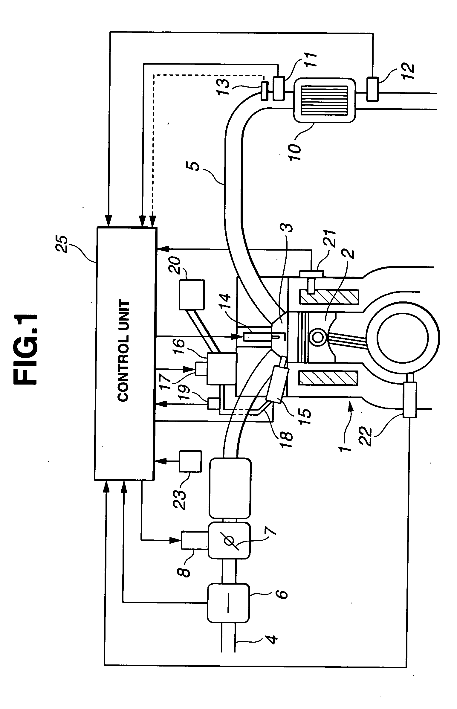
[0028] The first embodiment specifically refers to a combustion control system for direct-injection spark-ignition internal combustion engine 1 in which combustion chamber 3 of each engine cylinder is defined by piston 2 and connected with intake and exhaust passages 4 and 5 via intake and exhaust valves, respectively, as shown in FIG. 1. Engine 1 is herein provided with electronically controlled throttle valve 7, actuator 8, catalytic converter 10, spark plug 14, fuel injection valve 15, high-pressure fuel pump 16, pressure regulator valve 17, low-pressure fuel pump 20, control unit 25 and various detection units.

[0029] Throttle valve 7 is disposed in intake passage 4 and opened by actuator 8 to control a negative pressure in intake passage 4 under a control signal from control unit 25.

[0030] Fuel injection valve 15 is arranged on the intake side of combustion chamber 3 and o...

second embodiment

[0049] Next, the second embodiment will be explained below with reference to FIGS. 9A and 9B.

[0050] The second embodiment is similar to the first embodiment, except for the setting of the injection-to-ignition time interval T under the combustion retard control.

[0051] In the second embodiment, the injection-to-ignition time interval T is adjusted by shifting both of the fuel injection timing and the ignition timing as shown in FIGS. 9A and 9B. The injection-to-ignition time interval T reaches a minimum value Ta when the fuel injection timing and the ignition timing are most retarded within their respective ranges of the combustion retard control as shown in FIG. 9A and reaches the maximum value Tb when the fuel injection timing and the ignition timing are most advanced within their respective ranges of the combustion retard control as shown in FIG. 9B. The injection-to-ignition time interval T varies between the minimum value Ta and the maximum value Tb continuously and linearly wi...

third embodiment

[0052] Finally, the third embodiment will be explained below with reference to FIGS. 10A to 10C, 11A to 11C and 12.

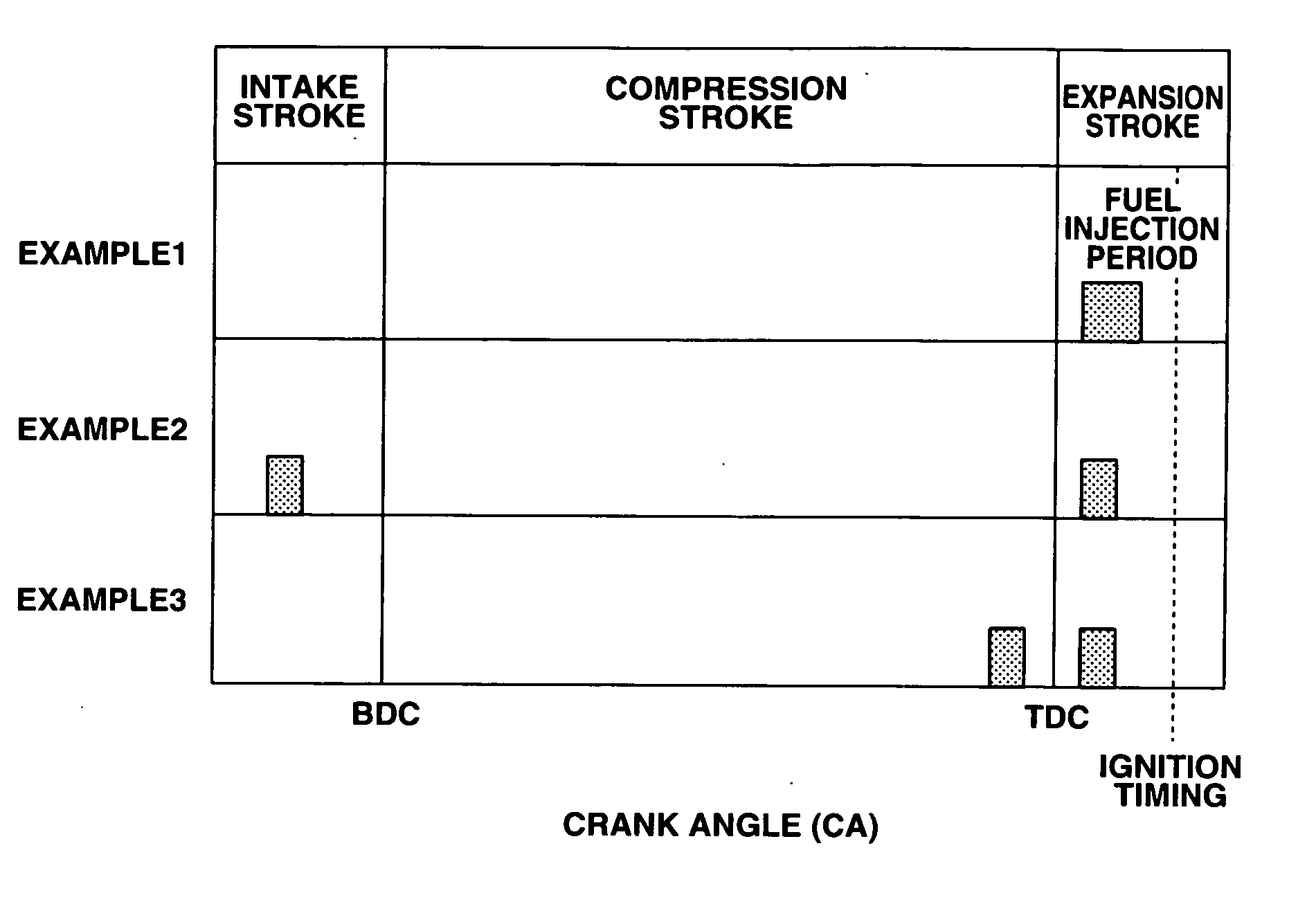
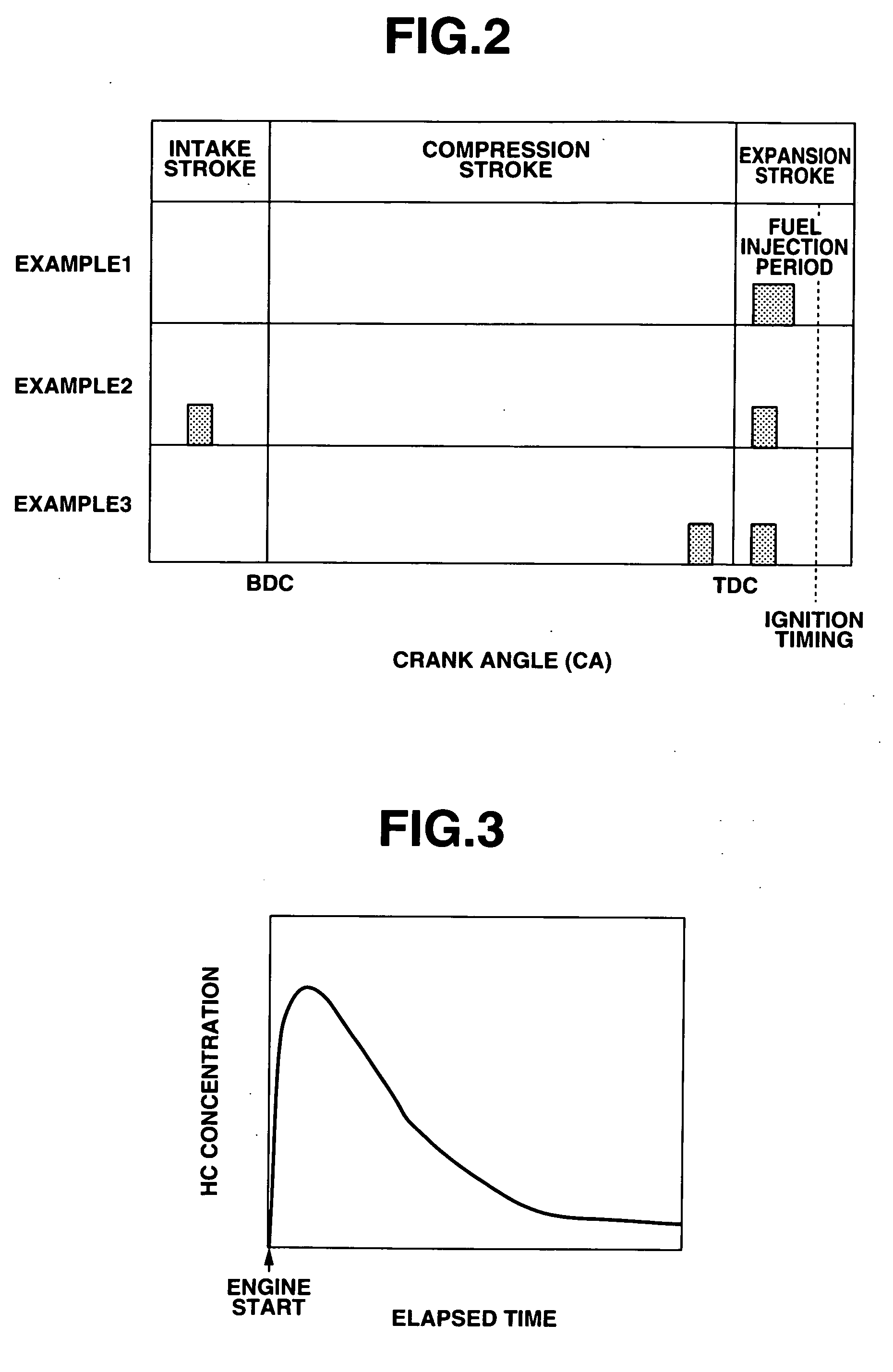
[0053] The third embodiment is similar to the first and second embodiments, except that the fuel injection is performed in two steps: intake- or compression-stroke injection and expansion-stroke injection as in Examples 2 and 3 by varying the ratio R of the amount of fuel injected at the expansion-stroke injection to the total amount of fuel injected at the intake- or compression-stroke and the expansion-stroke injection (hereinafter referred to as “expansion-stroke injection rate”) under the combustion retard control.

[0054] In the case of split fuel injection, the time from the later injection step to the spark ignition (the time for vaporization of fuel injected at the later injection step) is especially short. There thus arise an increase in the amount of unburned hydrocarbons and smoke in the exhaust gas due to insufficient fuel vaporization during a short time (e....


PUM


Abstract

There is provided a combustion control system for a direct-injection spark-ignition internal combustion engine, including a fuel injection valve that injects fuel directly into a cylinder of the engine to form an air-fuel mixture in a combustion chamber of the engine cylinder, a spark plug that ignites the air-fuel mixture, and a control unit that performs combustion retard control to set an ignition timing of the spark plug at a point after compression top dead center and set an injection period of the fuel injection valve at a time after compression top dead center and before the ignition timing in such a manner that a time interval from a start point of the injection period to the ignition timing increases with decrease in a temperature in the engine cylinder at a cold start of the engine.

Description

BACKGROUND OF THE INVENTION [0001] The present invention relates to a combustion control system and method for a direct-injection spark-ignition internal combustion engine and, more particularly, to a technique for controlling fuel injection timing and ignition timing of the engine in a cold start state where the early temperature rise (activation) of an exhaust catalytic converter is desired. [0002] Japanese Patent No. 3325230 proposes, as a technique for activating an exhaust catalytic converter in a direct-injection spark-ignition internal combustion engine, performing split fuel injection during a time from an intake stroke to ignition timing in a state where the catalytic converter has not been warmed up to its activation temperature. More specifically, the split fuel injection of Japanese Patent No. 3325230 includes at least two fuel injection steps: an earlier injection step carried out during the intake stroke to form an uniform and lean air-fuel mixture in a combustion cham...

Claims


Application Information

Patent Timeline
IPC IPC(8): F02D43/00
CPCF02D37/02F02D41/0255F02D41/061F02D41/064F02D41/068F02D41/1446F02D35/026F02D41/401F02D41/402F02D2041/389Y02T10/44Y02T10/26F02D41/3029Y02T10/12Y02T10/40
Inventor TAKEDA, TOMOYUKITOMITA, MASAYUKISAKAI, TARONAKAJIMA, AKIRAMAITANI, TAKAO
Owner NISSAN MOTOR CO LTD
Why Eureka
Try Eureka