
Catalyst nanoparticle

a catalyst nanoparticle and surface modification technology, applied in the direction of metal/metal-oxide/metal-hydroxide catalysts, physical/chemical process catalysts, cell components, etc., can solve the problems of high cost of catalyst nanoparticles with a particle diameter of 2-3 nm, and high cost of metal-based catalysts. achieve the effect of reducing catalytic activity

Inactive Publication Date: 2007-02-01
HITACHI LTD
View PDF30 Cites 66 Cited by
  • Summary
  • Abstract
  • Description
  • Claims
  • Application Information

AI Technical Summary

Benefits of technology

The patent text discusses the problem of catalyst nanoparticles aggregating and decreasing in catalytic activity over time in fuel cells, particularly in direct methanol fuel cells (DMFCs). This is due to the high surface energy of the nanoparticles and the transfer of catalyst nanoparticles onto support carbon. The patent proposes a solution by preparing catalyst nanoparticles with a porous inorganic oxide layer on the surface, which can enhance the stability and activity of the catalyst. This technology can improve the performance and durability of fuel cells, particularly those designed for portable and long-term use.

Problems solved by technology

Since such noble metal-based catalysts are expensive, the usage thereof is required to be as low as possible.
However, catalyst nanoparticles with a particle diameter of 2-3 nm have a very large surface energy and show dispersion instability.
Therefore, as the period of use of the catalyst is prolonged, a problem arises, namely the catalyst nanoparticles aggregate / agglomerate together and accordingly the catalyst metal surface area decreases, resulting in decreases in catalytic activity.
However, on the occasion of long-term use of PEFC electrodes, the transfer of catalyst nanoparticles on the support carbon cannot be avoided, and the catalyst nanoparticles that have been transferred aggregate / agglomerate together, possibly resulting in decreases in catalyst metal surface area and decreases in catalytic activity.
However, there is no report as yet about a technology of preparing Pt-containing nanoparticles with a porous inorganic oxide on the surface thereof.

Method used


Image

  • Catalyst nanoparticle
  • Catalyst nanoparticle
  • Catalyst nanoparticle

Examples


example 1

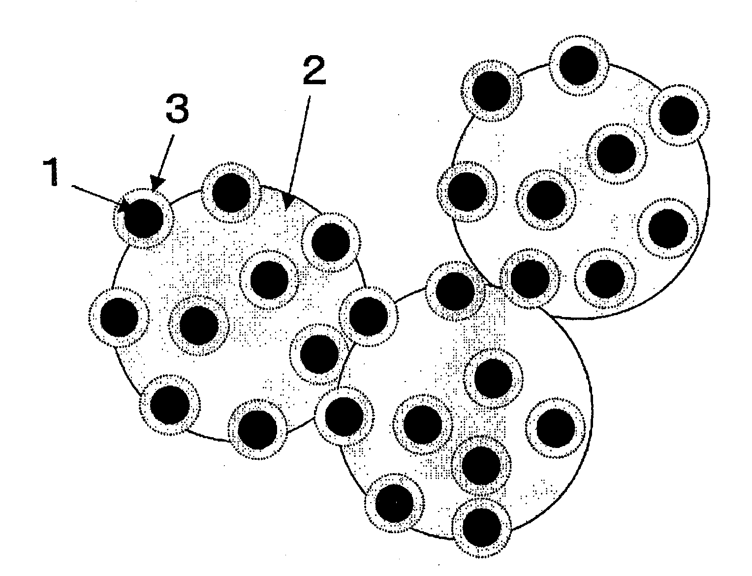
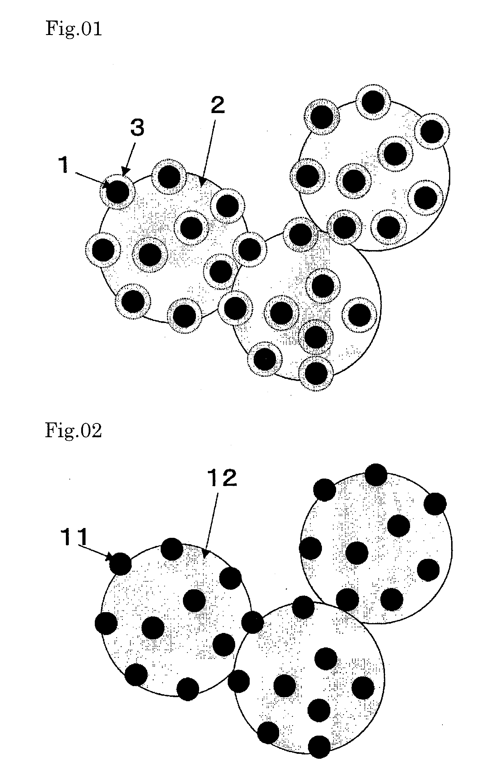
[0086]FIG. 1 is a schematic representation of a Pt—Ru alloy nanoparticle-carrying catalyst. The catalyst (catalyst Λ) shown in FIG. 1 was prepared in the following manner.

[0087] First, a colloidal solution of Pt—Ru alloy nanoparticles was prepared by adding an aqueous solution (33 mL) containing 128 mg of sodium borohydride (product of Wako Pure Chemical) dissolved therein to an aqueous solution (1967 mL) containing 63 mg of citric acid monohydrate (product of Wako Pure Chemical), 125 mg of chloroplatinic(IV) acid hexahydrate (product of Wako Pure Chemical) and 63 mg of ruthenium(III) chloride n-hydrate (product of Wako Pure Chemical) dissolved therein, and stirring the mixture for 1 day. It was confirmed by observation under a transmission electron microscope that the Pt—Ru alloy nanoparticles obtained had a particle diameter of about 2 nm, as described later herein.

[0088] Thereafter, an aqueous solution (250 μl) containing 0.842 μl of 3-aminopropyltrimethoxysilane (product of Al...

example 2

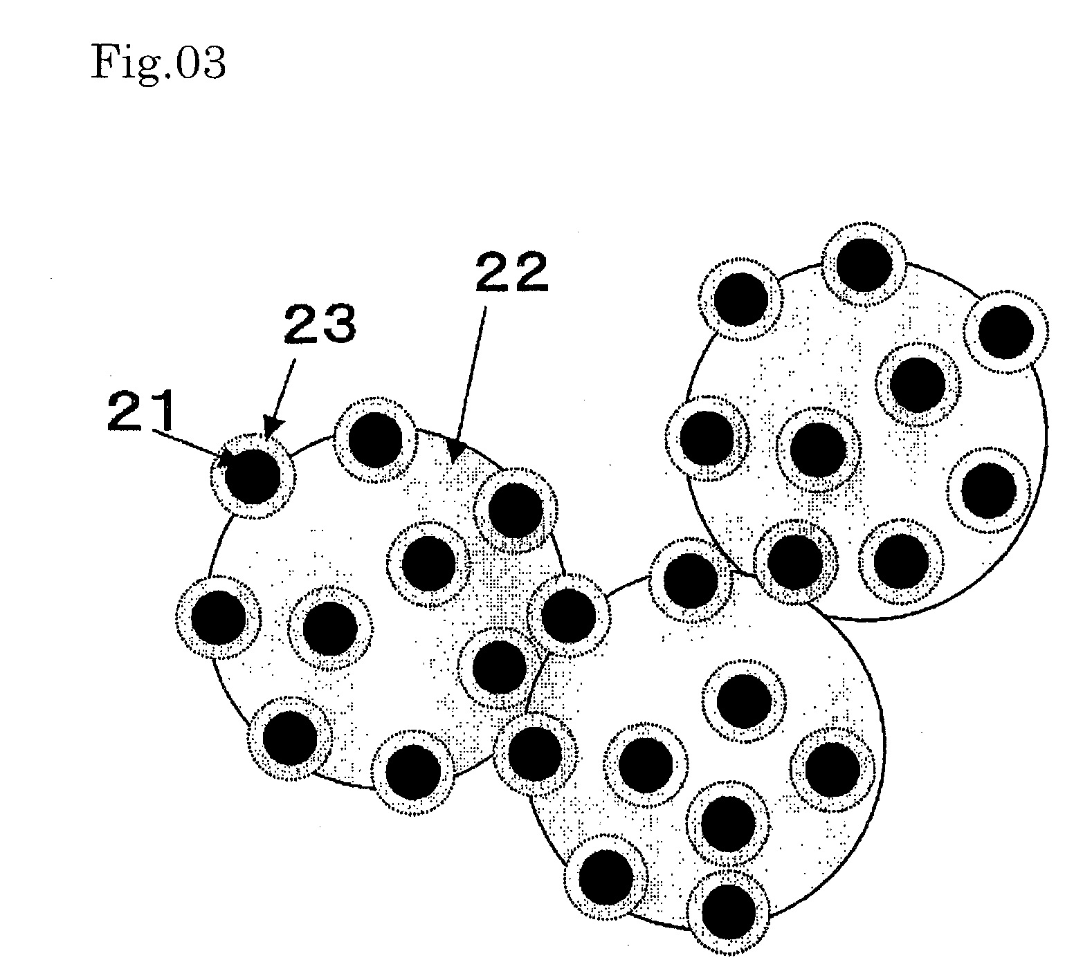
[0094]FIG. 3 is a schematic representation of a Pt nanoparticle-carrying catalyst. The catalyst shown in FIG. 3 (catalyst C) was produced in the following manner.

[0095] First, a colloidal solution of Pt nanoparticles was prepared by adding an aqueous solution (33 mL) containing 128 mg of sodium borohydride (product of Wako Pure Chemical) dissolved therein to an aqueous solution (1967 mL) containing 63 mg of citric acid monohydrate (product of Wako Pure Chemical) and 250 mg of chloroplatinic(IV) acid hexahydrate (product of Wako Pure Chemical) dissolved therein, and stirring the mixture for 1 day. Then, an aqueous solution (250 μl) containing 0.842 μl of 3-aminopropyltrimethoxysilane (product of Aldrich) dissolved therein was added. After 20 minutes, 80 mL of an aqueous solution of sodium silicate as adjusted to pH 10.5 was added, and the resulting mixture was stirred for 2 days to coat the nanoparticles with porous SiO2. To this solution was added an aqueous dispersion (20 mL) of 2...


PUM

PropertyMeasurementUnit
particle diameteraaaaaaaaaa

Abstract

Although nanoparticles capable of providing an extremely large active surface area have highly marked advantages, when a PEFC electrode utilizing nanoparticles is used for a prolonged period of time, the catalyst nanoparticles on carrier of the PEFC electrode because of the nano-size thereof migrate and aggregate together to result in a rapid loss of activity. Thus, there is a demand for inhibition of the above aggregation so as to prevent any drop of catalytic activity. According to the present invention the aggregation of nanoparticles can be inhibited by catalyst nanoparticles containing Pt wherein a porous matter containing an inorganic oxide is disposed on the surface of the catalyst nanoparticles. When use is made of nanoparticles whose surface has undergone specific modification, excellent activity can be realized. Therefore, there are provided surface-modified nanoparticles and catalyst and further a PEFC electrode utilizing these nanoparticles.

Description

TECHNICAL FIELD [0001] This invention relates to surface-modified catalyst nanoparticles and to an application thereof. BACKGROUND ART [0002] Fuel cells, which have the possibility of attaining an energy density 10 times as high as that of lithium ion secondary batteries and can be carried anywhere provided that a fuel is carried with it, are expected to bring about great changes in criteria for designing mobile machines and tools. In particular, direct methanol fuel cells (DMFCs), which use methanol as the fuel, are expected to be rendered small-sized and lightweight and become low-cost. Further, much attention is also focused on such characteristics thereof that, in spite of their being small-sized, they are excellent in startability, responsiveness to load, and stability as power sources capable of satisfying those long-period drive requirements imposed by portable apparatus, typically cellular phones and notebook computers, and can generate electricity so long as a fuel is fed t...

Claims


Application Information

Patent Timeline
Patent Type & Authority Applications(United States)
IPC IPC(8): H01M4/92B01J23/44H01M4/88B01J21/08B01J23/42B01J23/46B01J37/02B01J37/16B22F1/054B22F1/16B22F9/24H01M4/86H01M8/10
CPCB01J21/08Y10S977/775B01J23/462B22F1/0018B22F1/02B22F2998/10B82Y30/00H01M4/8657H01M4/92H01M4/926H01M8/1002Y02E60/521B01J23/42Y10S977/81Y10S977/811Y10T428/2991Y10S977/773B22F9/24H01M8/1007Y02E60/50B22F1/054B22F1/16
Inventor SHIMAZAKI, YUZURUKOBAYASHI, YOSHIOKONNO, MIKIO
Owner HITACHI LTD
Learn More