Method and system for detecting fluorescence from microarray disk

a microarray disk and fluorescence detection technology, applied in fluorescence/phosphorescence, laboratory glassware, instruments, etc., can solve the problems of reducing the signal-to-noise ratio in the signal indicating, the difficulty of downsizing the above device, and the noise of excitation light, etc., to achieve high signal-to-noise ratio and high signal-to-noise ratio

Inactive Publication Date: 2007-02-01
FUJIFILM HLDG CORP +1
View PDF7 Cites 11 Cited by
  • Summary
  • Abstract
  • Description
  • Claims
  • Application Information

AI Technical Summary

Benefits of technology

[0018] The first object of the present invention is to provide a fluorescence detection method which detects fluorescence emitted from specimens on a substrate disk (microarray disk), and can achieve a high signal-to-noise ratio in the signal indicating the detected fluorescence.
[0019] The second object of the present invention is to provide a fluorescence detection system which detects fluorescence emitted from specimens on a substrate disk (microarray disk), and can achieve a high signal-to-noise ratio in the signal indicating the detected fluorescence.
[0022] In the fluorescence detection method according to the first aspect of the present invention and the fluorescence detection system according to the second aspect of the present invention, the irradiation with the excitation light is performed while the substrate disk is rotated, and the fluorescence emitted from each of the one or more biological specimens is detected when a predetermined time elapses since the biological specimen is irradiated. That is, delayed fluorescence is detected. Since the fluorescence is detected after irradiation with the excitation light is completed, the excitation light does not enter the fluorescence-detection unit. Therefore, the fluorescence-detection unit is free from the noise produced by the excitation light, and can output a detection signal with high signal-to-noise ratio.
[0026] (iii) The specimen-holding area may be realized by one or more grooves spirally or concentrically arranged on the substrate disk. In this case, it is possible to prevent irradiation of a spot adjacent to an objective spot when the one or more biological specimens are fixed in a plurality of spots on the substrate disk.
[0028] (v) The substrate disk maybe opaque to the excitation light. In this case, it is possible to prevent propagation of the excitation light through the substrate disk, and undesirable excitation of biological specimens in the vicinity of the objective spot to which the excitation light is applied.

Problems solved by technology

However, in the line scanning system, it is necessary to repetitively move an excitation-light irradiation unit and a fluorescence reception unit, so that the inertia management in the mechanical units is required, and it is difficult to downsize the above device.
However, when the excitation light enters the fluorescence detector, the excitation light produces noise, and lowers the signal-to-noise ratio in the signal indicating the detected fluorescence.
Nevertheless, the above optical filter cannot completely prevent entrance of the excitation light into the fluorescence detector.
Therefore, conventionally, it is difficult to achieve sufficient signal-to-noise ratio in the signal indicating the detected fluorescence.

Method used


Image

  • Method and system for detecting fluorescence from microarray disk
  • Method and system for detecting fluorescence from microarray disk
  • Method and system for detecting fluorescence from microarray disk

Examples


first embodiment

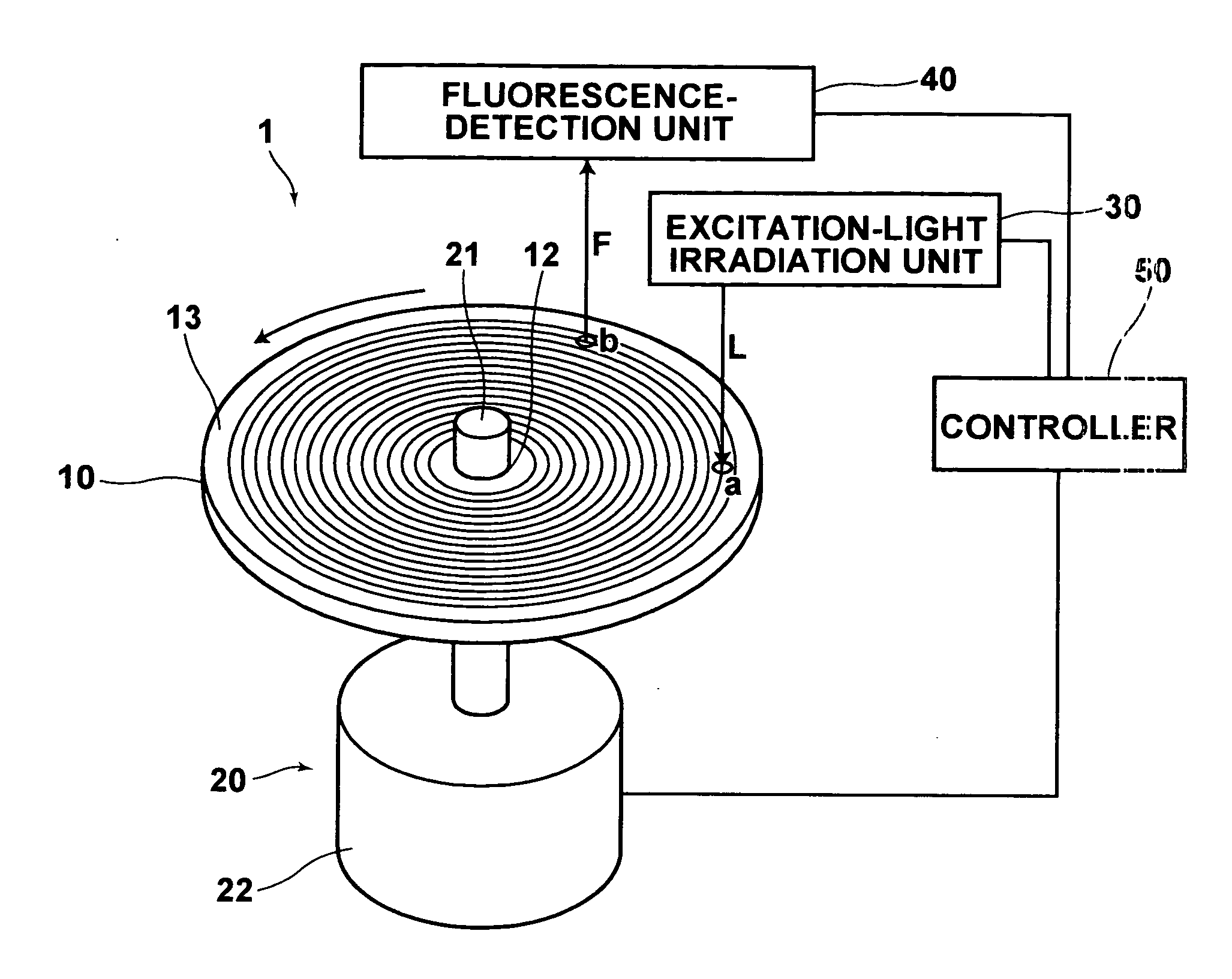
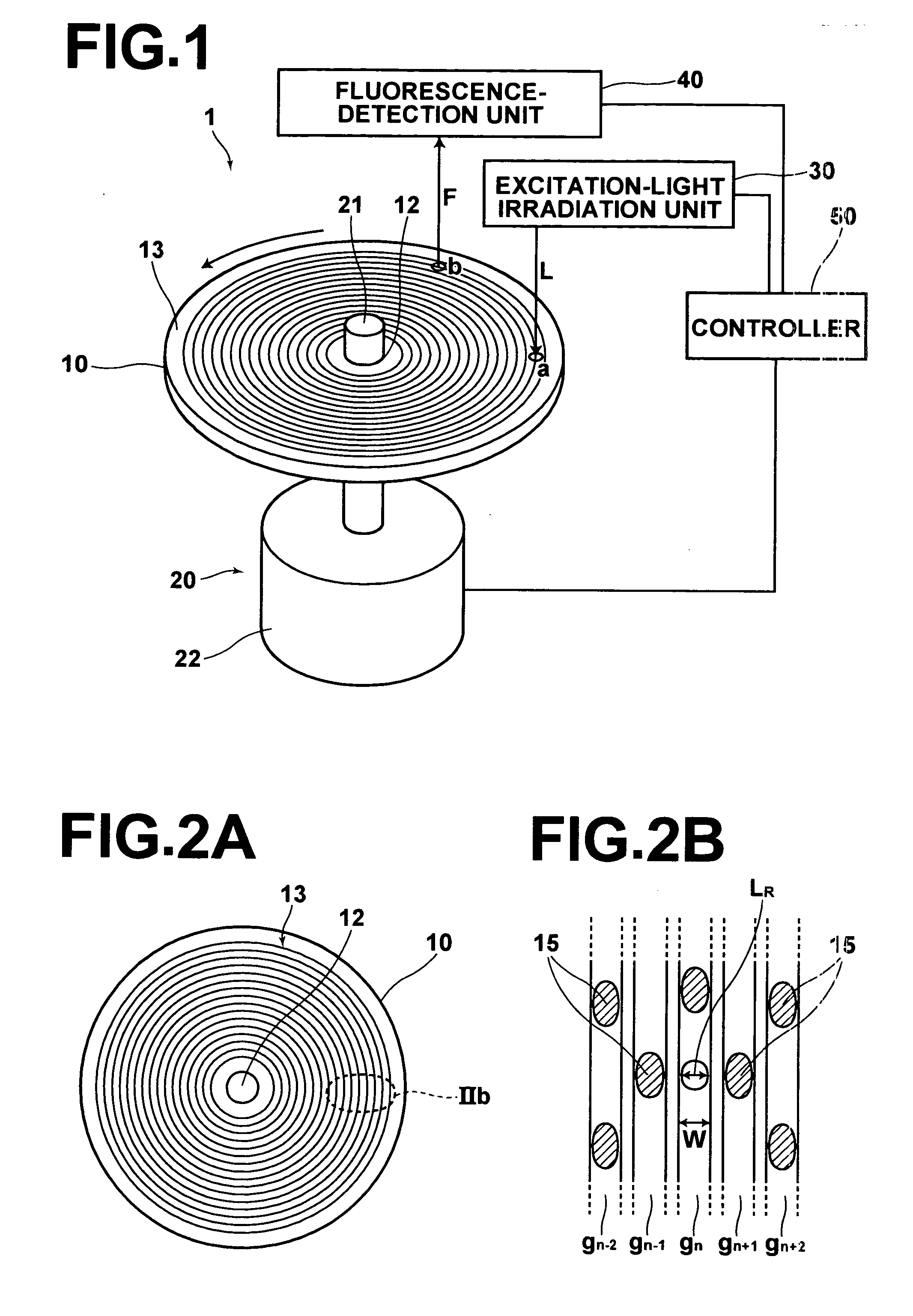
[0035]FIG. 1 is a diagram schematically illustrating a fluorescence detection system according to the first embodiment of the present invention.

[0036] As illustrated in FIG. 1, the fluorescence detection system 1 according to the first embodiment comprises a microarray disk 10, a rotation unit 20, an excitation-light irradiation unit 30, a fluorescence-detection unit 40, and a controller 50.

[0037] The microarray disk 10 is constituted by a rotatable substrate disk, where a surface of the microarray disk 10 includes a specimen-holding area, and fluorescence-labeled biological specimens are fixed on the specimen-holding area. The rotation unit 20 rotates the microarray disk 10. The excitation-light irradiation unit 30 irradiates each of the biological specimens (fixed on the microarray disk 10) with excitation light L. The fluorescence-detection unit 40 detects fluorescence F emitted from each of the biological specimens. The controller 50 controls the rotation unit 20, the excitati...

second embodiment

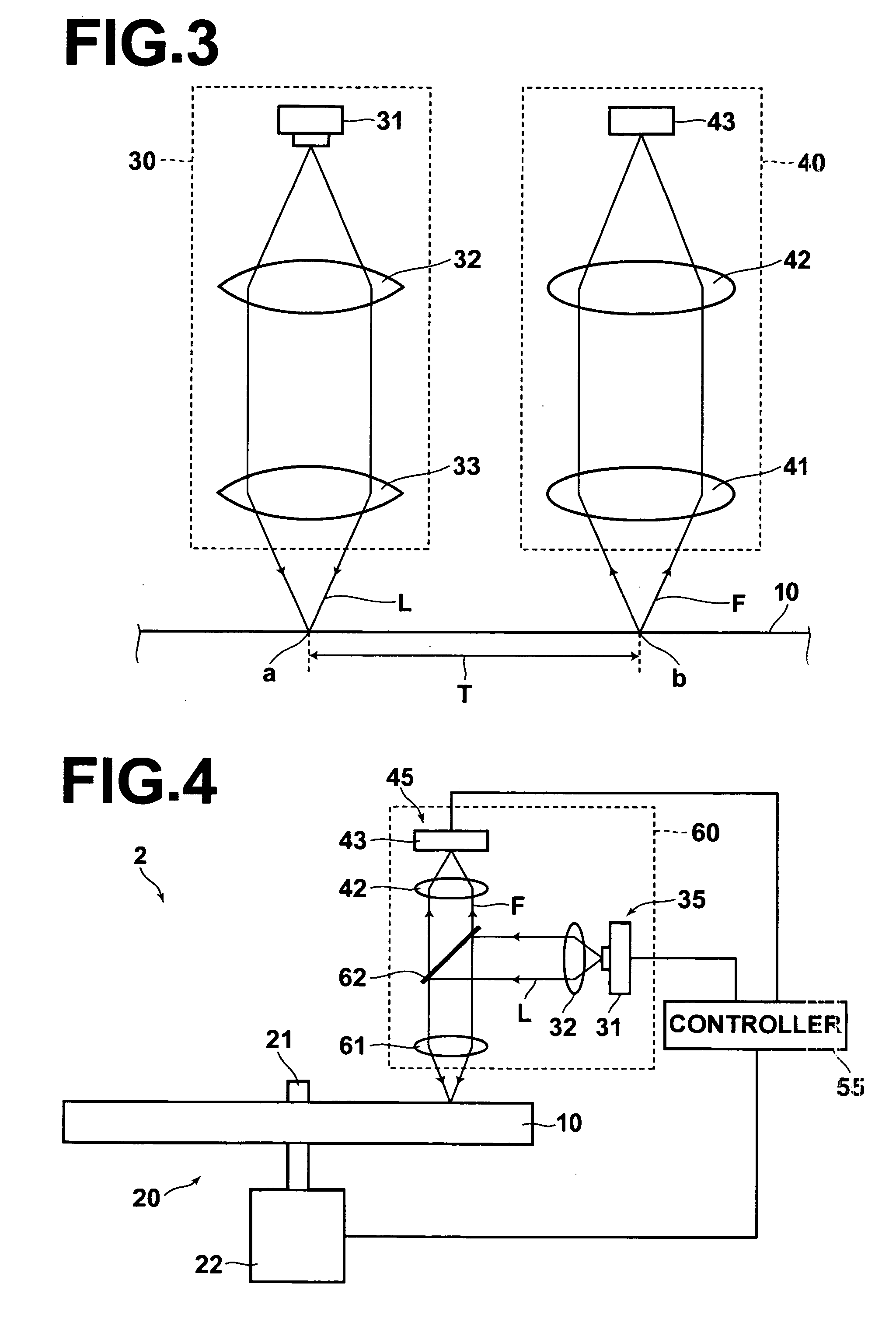
[0062]FIG. 4 is a diagram schematically illustrating a fluorescence detection system according to the second embodiment of the present invention.

[0063] The fluorescence detection system 2 according to the second embodiment is different from the fluorescence detection system 1 according to the first embodiment in that an excitation-light irradiation unit 35 and a fluorescence-detection unit 45 are integrally formed in an optical unit 60.

[0064] The optical unit 60 comprises a condensing lens 61 and a half mirror 62. The condensing lens 61 is arranged above the specimen-fixed side of the microarray disk 10, makes the excitation light L converge on each biological specimen, and collects fluorescence F emitted from the biological specimen. The half mirror 62 is arranged above the condensing lens 61, passes the fluorescence F, and reflects the excitation light L.

[0065] The optical unit 60 operates as follows.

[0066] The excitation light L is emitted from the laser diode 31, collimated ...


PUM

PropertyMeasurementUnit
diameteraaaaaaaaaa
diameteraaaaaaaaaa
angleaaaaaaaaaa

Abstract

In a fluorescence detection method: each of one or more biological specimens is irradiated with excitation light while a substrate disk is rotated, where the one or more biological specimens are labeled with a fluorescent material and fixed on the substrate disk. Fluorescence which is emitted from each of the one or more biological specimens is detected when a predetermined time elapses since the biological specimen is irradiated with the excitation light.

Description

BACKGROUND OF THE INVENTION [0001] 1. Field of the Invention [0002] The present invention relates to a fluorescence detection method and a fluorescence detection system in which a fluorescence-labeled biological specimen is irradiated with excitation light, and fluorescence emitted from the biological specimen by the irradiation is detected. [0003] 2. Description of the Related Art [0004] Conventionally, the fluorescence detection systems which use fluorescent material as a labeling material are known in the field of biochemistry. It is possible to investigate gene arrangement or gene expression levels, isolate or identify protein, or evaluate molecular weight or characteristics of protein, by reading fluorescent images obtained by use of a fluorescence detection system. [0005] For example, a fluorescent dye is added to a solution containing DNA fragments which are to be electrophoresed, and thereafter the DNA fragments are electrophoresed on a gel support. Alternatively, DNA fragme...

Claims


Application Information

Patent Timeline
Patent Type & Authority Applications(United States)
IPC IPC(8): G01N21/64
CPCB01L3/5085B01L3/5088B01L2300/0636G01N35/00069G01N21/6428G01N21/6456B01L2300/0806
Inventor IKAMI, SEISHI
Owner FUJIFILM HLDG CORP
Why Eureka
Try Eureka