
Stent delivery and guidewire systems

Inactive Publication Date: 2007-02-01
BIOSENSORS INT GROUP
View PDF99 Cites 128 Cited by
  • Summary
  • Abstract
  • Description
  • Claims
  • Application Information

AI Technical Summary

Benefits of technology

[0016] In any medical procedure, saving surgical steps offers advantages both in terms of economic efficiency and improving patient care by requiring less time engaging in invasive activity. In stent procedures, over-the-wire stent delivery systems can offer such benefits. With a system that is able to be advanced over a guidewire and later removed following stent deployment, one avoids the need for exchanging the guidewire for the delivery device before and / or after the stent delivery procedure. The present invention offers such benefits, but in a higher performance package able to access and deliver one or more stents to sites including the neurovasculature, especially within the brain, and small vessels, particularly distal coronary arteries.
[0020] An inner sleeve or tubular member is provided over the corewire / guidewire. An outer sleeve or tubular sheath is provided to restrain one or more stents carried by the delivery device. The inner sleeve serves to fill space between the guidewire core and external sheath. Employing an inner sleeve as opposed to a thicker wall sheath and / or an increased diameter core member offers a number of advantages ranging from system preparation to flexibility / trackability performance as elaborated upon below in connection with the drawings.
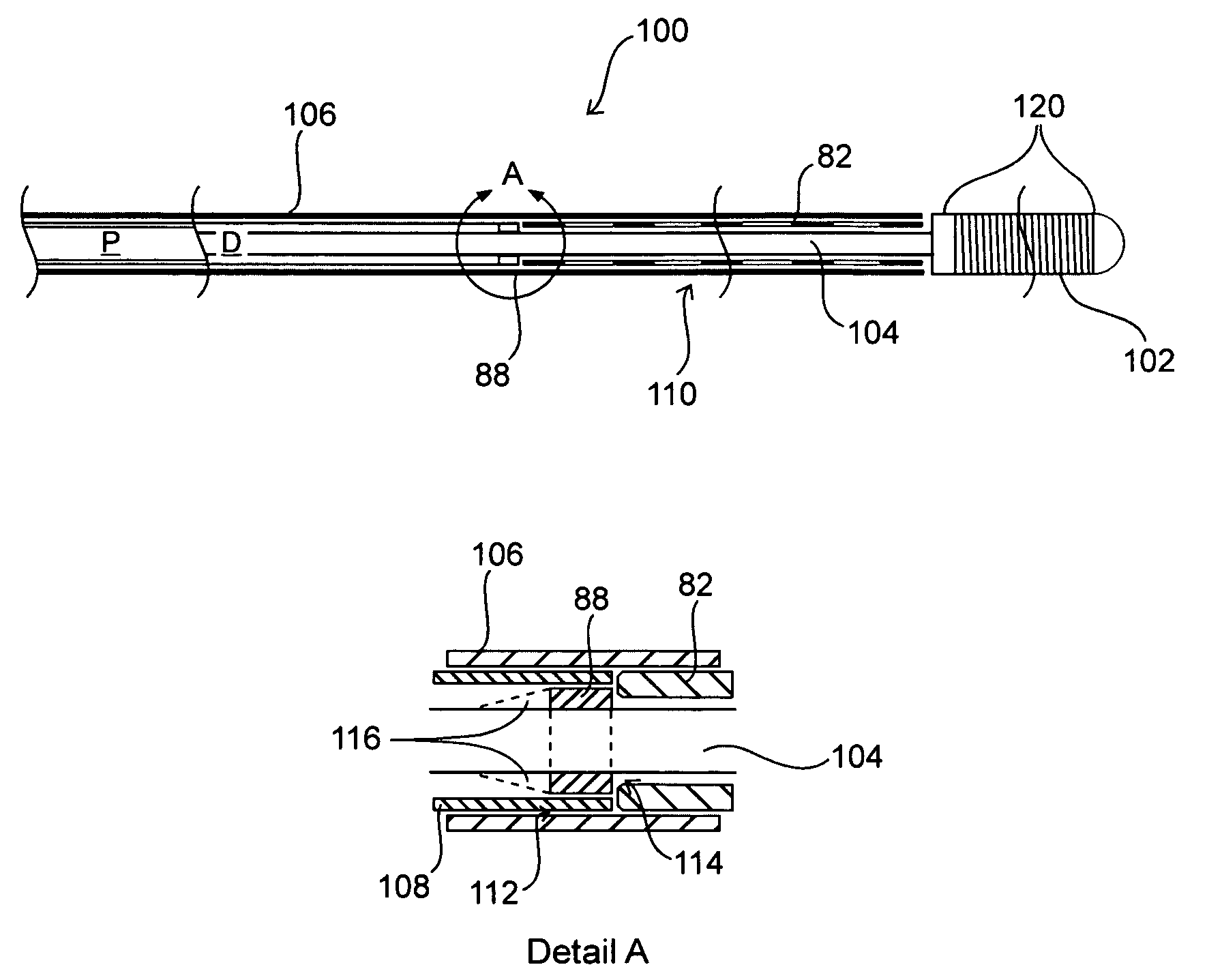
[0023] After stent delivery by partial withdrawal of the outer sleeve, each of the inner and outer sleeves may be removed. With the device utilizing the combination blocker approach, the stent abutment feature then has a profile which is low enough so that it does not interfere with subsequent use of the core member as a fully functional guidewire. In this manner, a balloon catheter or another member can be advanced over the core member after removal of the other system components. Especially where the abutment / blocker member steps-up by about 0.002 inch over an adjacent section (i.e., when it is 0.004 greater in diameter for round sections), then a ramp is advantageously provided on the proximal side of the feature to provide an improved transition.
[0025] In instances where the inner sleeve terminates proximal to the blocker member and / or the blocker member may be too large to allow a catheter to pass over the feature, the corewire still offers certain utility. For example, the wire may be advanced so that the blocker is distal to the stent delivered and next advancing a balloon catheter to effect post-dilatation at the lesion site.
[0026] While there may be circumstances in which the corewire should not or cannot be advanced as described, this variation of the invention may be desirable for reasons of ease of construction and robustness in design. Yet, the other variation of the invention facilitates a more complete set of options for using the guidewire after its sleeve elements are removed.
[0028] If not fully split or splittabe such that they can simply be pulled off the corewire directly, the sleeves may instead be withdrawn proximally up to a point where any closed portion remains over the guidewire / corewire. A physician may then switch his grip from a proximal location to the sleeve portions, to distal of them—even with a wire between about 150 and about 180 cm in length. Alternatively, a longer 300 cm “exchange length” wire or “dock” type system could be used to provide an overall length that allows the sleeves to be withdrawn clear of the wire while holding a proximal portion of the device / assembly. In any case, the option of removing the inner and outer sleeves from the corewire of the device offers a physician a bare wire (upon optional handle removal) for use in a vessel without altering or disturbing a distal position of the wire.

Problems solved by technology

Problems encountered with known delivery systems include drawbacks ranging from failure to provide means to enable precise stent placement, to bulkiness of system design.
Inefficient design prohibits scaling systems to sizes as small as necessary to enable difficult access or small-vessel procedures (i.e., in tortuous vasculature or vessels having a diameter less than 3 mm, even less than 2 mm).
Irrespective of their various asserted advantages, all of these known sheath / pusher systems are limited in the degree to which they can be miniturized.
The limiting factor is that the pusher must have sufficient wall thickness to offer an adequate interface to abut the stent when withdrawing the sheath or when pushing the stent out of the sheath.
That is, with stent delivery system in its pre-deployment configuration, a substantial gap exists between the outside of the stent and the inside of the sheath.
As is commonly known, stents relying on shape memory alloy (SMA) thermally-driven shape recovery / change to open can be disadvantageous for reasons ranging from unpredictable deployment (due to even small variations in Afinish temperature, for reason of inadvertent heating during deployment, etc.) to a requirement that environmental controls be employed in device storage.

Method used


Image

  • Stent delivery and guidewire systems
  • Stent delivery and guidewire systems
  • Stent delivery and guidewire systems

Examples


Embodiment Construction

[0049] Various exemplary embodiments of the invention are described below. Reference is made to these examples in a non-limiting sense. They are provided to illustrate more broadly applicable aspects of the present invention. Various changes may be made to the invention described and equivalents may be substituted without departing from the true spirit and scope of the invention. In addition, many modifications may be made to adapt a particular situation, material, composition of matter, process, process act(s) or step(s) to the objective(s), spirit or scope of the present invention. All such modifications are intended to be within the scope of the claims made herein.

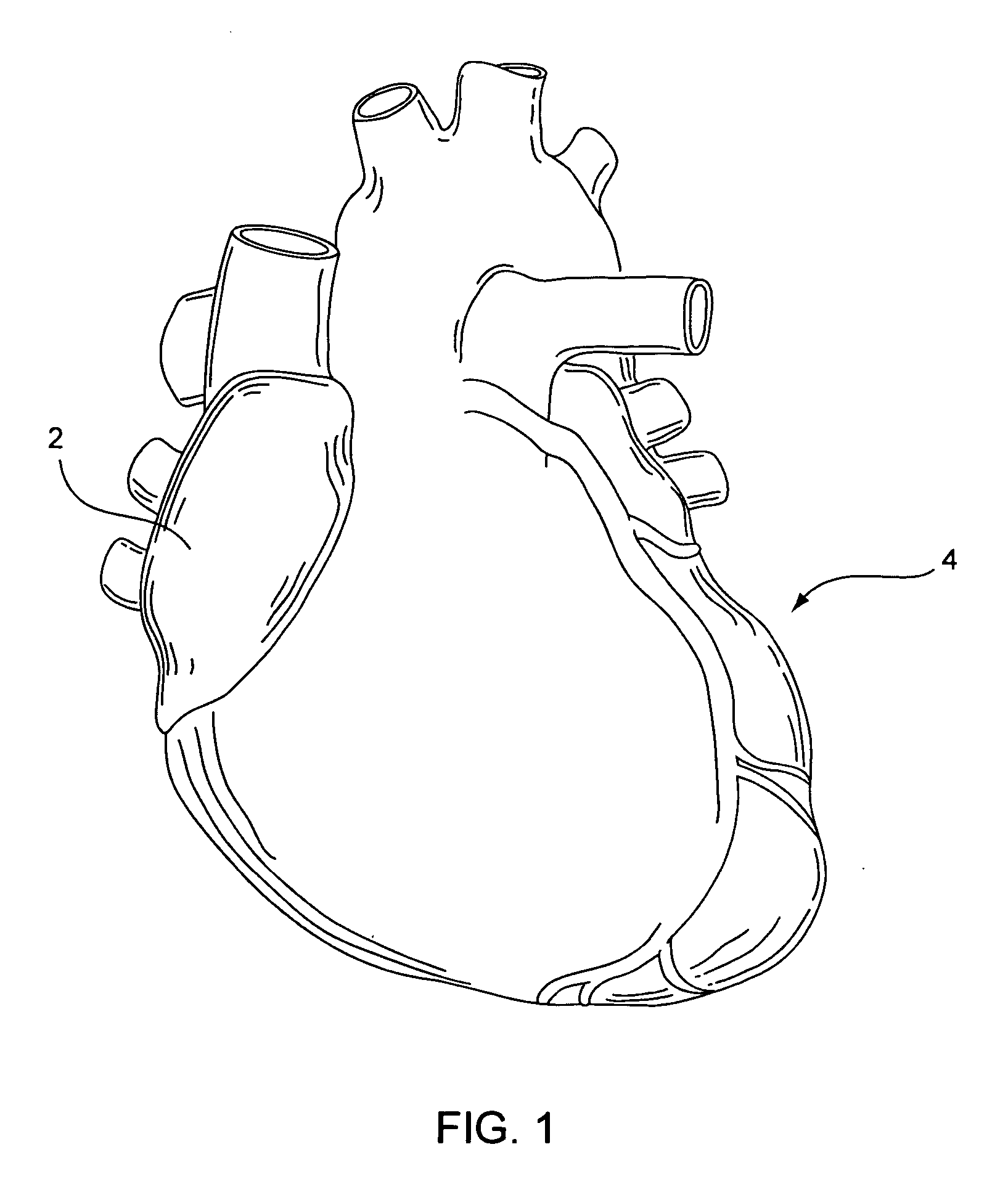
[0050] In light of this framework, FIG. 1 shows a heart 2 in which its vessels may be the subject of one or more angioplasty and / or stenting procedures. To date, however, significant difficulty or impossibility is confronted in reaching smaller coronary arteries 4. If a stent and a delivery system could be provided for...


PUM


Abstract

Medical device and methods for delivery or implantation of prostheses within hollow body organs and vessels or other luminal anatomy are disclosed. The subject technologies may be used in the treatment of atherosclerosis in stenting procedures.

Description

CROSS-REFERENCE TO RELATED APPLICATIONS [0001] This application claims the benefit of U.S. Provisional Application Ser. No. 60 / 690,937, filed on Jun. 14, 2005, and U.S. patent application Ser. No. 11 / 241,802 filed on Sep. 29, 2005, incorporated by reference in their entireties.BACKGROUND OF THE INVENTION [0002] Implants such as stents and occlusive coils have been used in patients for a wide variety of reasons. One of the most common “stenting” procedures is carried out in connection with the treatment of atherosclerosis, a disease that results in a narrowing and stenosis of body lumens, such as the coronary arteries. At the site of the narrowing (i.e., the site of a lesion) a balloon is typically dilatated in an angioplasty procedure to open the vessel. A stent is set in apposition to the interior surface of the lumen in order to help maintain an open passageway. This result may be affected by means of scaffolding support alone or in coordinated use with one or more drugs carried b...

Claims


Application Information

Patent Timeline
IPC IPC(8): A61F2/06
CPCA61F2/013A61F2/95A61F2230/0067A61F2002/9665A61F2002/018A61F2/97
Inventor CHANG, JEAN C.PANDYA, SUDIP R.
Owner BIOSENSORS INT GROUP
Learn More