
Crucible apparatus and method of solidifying a molten material

a technology of crucible and solidification method, which is applied in the direction of lighting and heating apparatus, under a protective fluid, etc., can solve the problems of destroying the crucible, reducing the cost of refining scrap silicon, and inability to reuse the crucible, so as to achieve efficient and low-cost refining. the effect of the material cos

Inactive Publication Date: 2007-02-08
IIS MATERIALS CORP
View PDF28 Cites 21 Cited by
  • Summary
  • Abstract
  • Description
  • Claims
  • Application Information

AI Technical Summary

Benefits of technology

[0007] The crucible body may have a slit formed from its upper end to its lower end. Alternatively, the crucible body may be tapered such that the diameter of its upper end is slightly larger than the diameter of its lower end. When the crucible body has a slit or a taper, an excessive force is not applied to the crucible body if the molten material expands during the process of solidification, so cracks can be prevented from forming in the crucible body during solidification.
[0010] According to another form of the present invention, a crucible apparatus includes a plurality of hollow crucible bodies, each of which is open at its upper and lower ends, and a rotatable table which can support the plurality of crucible bodies and close off the lower ends of the crucible bodies. A plurality of receiving spaces for receiving molten material are defined by placing the crucible bodies on the rotatable table. Due to the provision of a plurality of crucible bodies, it is possible to achieve a higher throughput by manufacturing a plurality of silicon ingots at the same time.
[0012] Each crucible body may have a slit formed from its upper end to its lower end. Alternatively, each crucible body may be tapered such that the diameter of its upper end is slightly larger than the diameter of its lower end. As described above, when a crucible body has a slit or a taper, an excessive force is not applied to the crucible body if the molten material expands during the process of solidification, so cracks can be prevented from forming in the crucible body.
[0014] Prior to pouring the molten material into the receiving spaces defined by the crucible bodies, a solid material is preferably introduced into the bottom of each receiving space so as to substantially cover the bottom of the receiving space. In the same manner as described above, the solid material prevents molten material which is poured into the space from directly contacting the bottom surface of the space, whereby components of the crucible can be prevented from being mixed with the molten material due to thermal shock. The solid material preferably comprises the same substance as the molten material.
[0015] With a crucible apparatus and solidification method according to the present invention, a crucible body can be repeatedly used, so not only can material costs of refining be decreased, but removal of solidified material is facilitated, so refining can be efficiently carried out.

Problems solved by technology

However, in order to remove solidified silicon from such a crucible, it is necessary to destroy the crucible, so the crucible cannot be reused.
A quartz crucible is extremely expensive, so the need to destroy the crucible increases the cost of refining scrap silicon.

Method used


Image

  • Crucible apparatus and method of solidifying a molten material
  • Crucible apparatus and method of solidifying a molten material
  • Crucible apparatus and method of solidifying a molten material

Examples


first embodiment

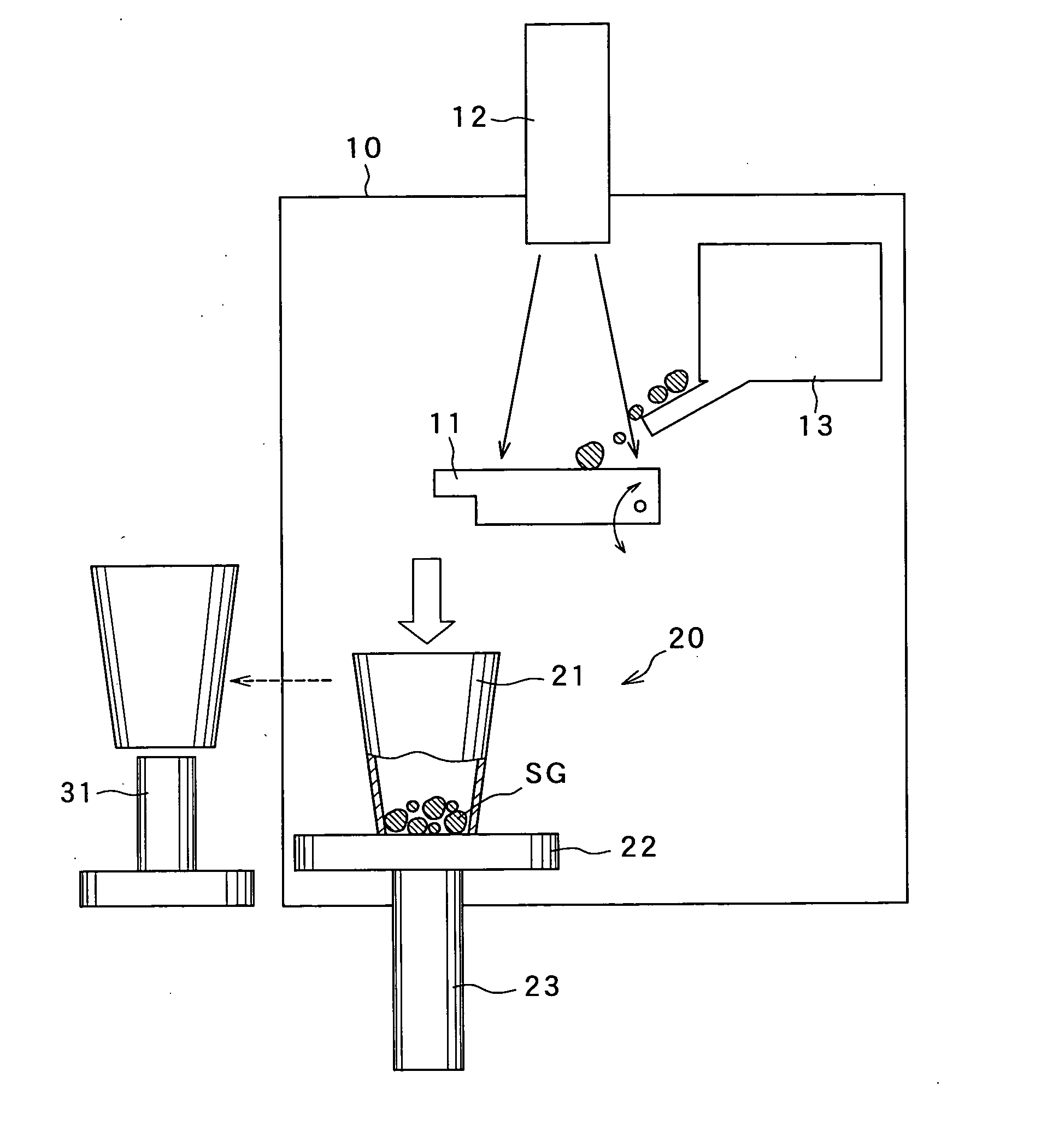
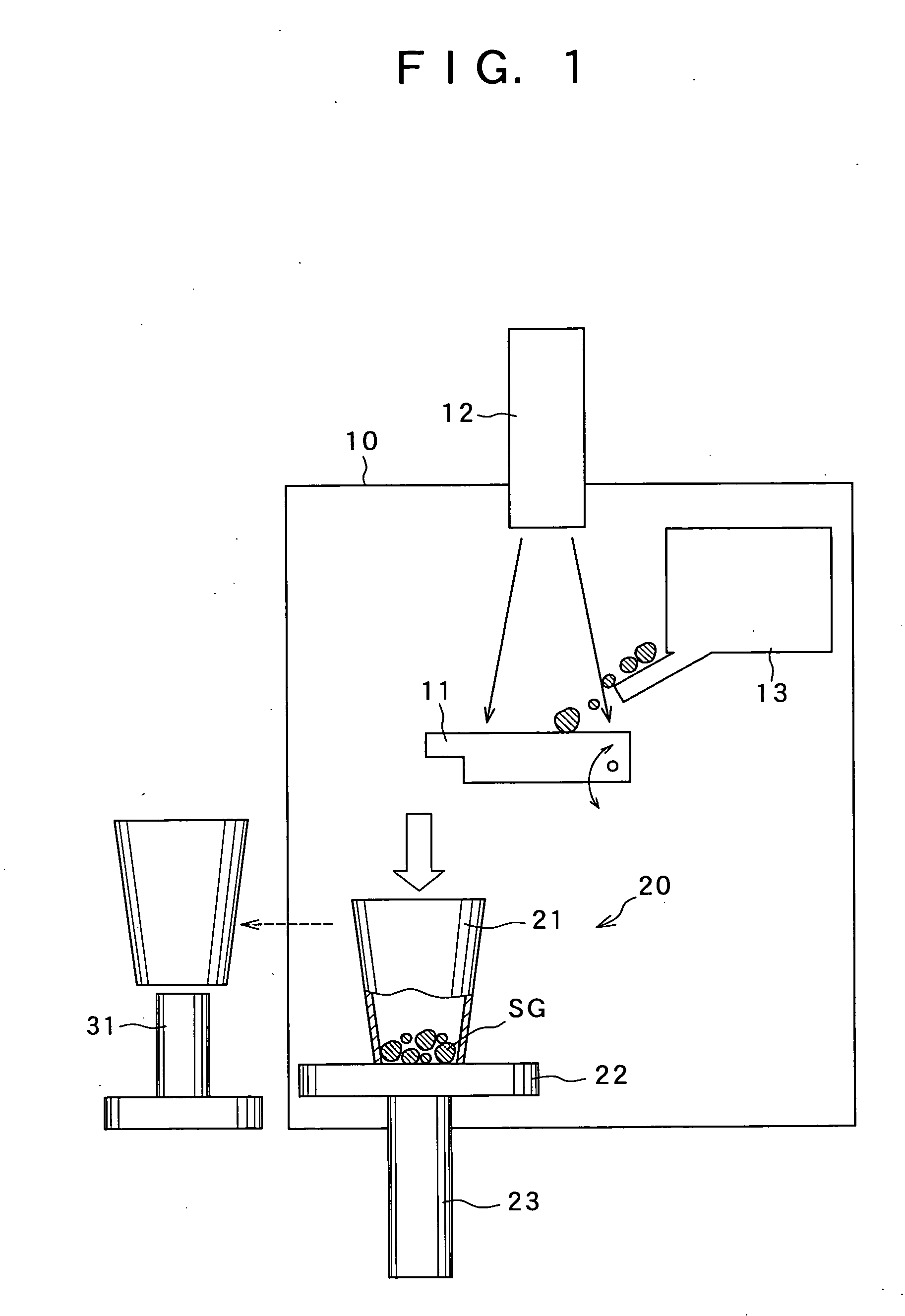
[0022]FIG. 1 schematically illustrates an electron beam refining apparatus equipped with a crucible apparatus according to the present invention. As shown in FIG. 1, the electron beam refining apparatus includes a vacuum chamber 10 in which a tiltable hearth 11, a material supply unit 13, and a crucible apparatus 20 are provided. Lumps of silicon which were previously obtained by crushing scrap silicon are successively supplied from the supply unit 13 to the hearth 11, in which they are melted by an electron beam from an electron beam generating unit 12 disposed at the upper end of the vacuum chamber 10. The melting evaporates impurities contained in the scrap silicon to obtain molten silicon of high purity. The hearth 11 is then tilted, and molten silicon is poured from the hearth 11 into the crucible apparatus 20. The molten silicon is solidified inside the crucible apparatus 20 to form a high purity silicon ingot.

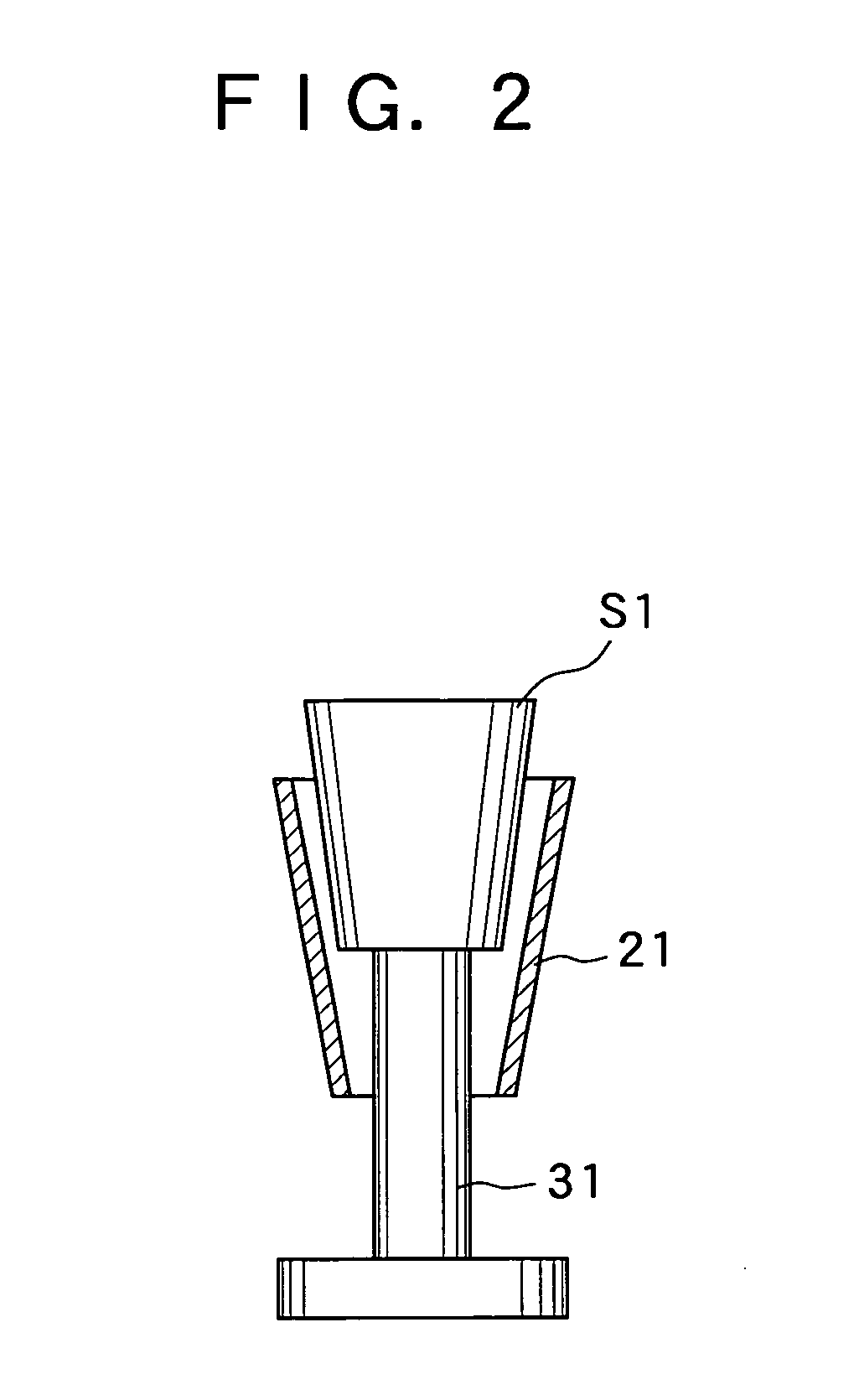
[0023] The crucible apparatus 20 comprises a hollow crucible body 2...

second embodiment

[0030]FIGS. 3 and 4 illustrate a crucible apparatus 20 according to the present invention. In this embodiment, the crucible apparatus 20 comprises a cylindrical crucible body 21 made of graphite which is open at its upper and lower ends and a circular bottom plate 22 which closes off the lower end of the crucible body 21. The crucible body 21 can be disposed atop the bottom plate 22 in the same manner as in the previous embodiment. A slit 24 is formed completely through the wall thickness of the crucible body 21 over its entire length from its upper end to its lower end. The slit 24 enables the crucible body 21 to be deformed in the radial direction and the circumferential direction. The bottom plate 22 is made of copper, and as in the previous embodiment, a helical passage through which cooling water which is supplied from an unillustrated cooling water supply can circulate is formed in its interior. Due to the high melting point of graphite it is not necessary to provide a cooling...

third embodiment

[0031] a crucible apparatus according to the present invention will next be described while referring to FIGS. 5 and 6. FIG. 5 is a schematic elevation of an electron beam refining apparatus employing this embodiment of a crucible apparatus, and FIG. 6 is a plan view of the crucible apparatus of FIG. 5. The overall structure of the refining apparatus shown in FIG. 5 is similar to that of the refining apparatus of FIG. 1, so the same components as in FIG. 1 are indicated by the same symbols, and the following explanation will concentrate on components which are different in structure from in FIG. 1.

[0032] As shown in FIG. 5, a vacuum chamber 10 houses a tiltable hearth 11, a material supply unit 13, and a crucible apparatus 50. An electron beam generating unit 12 is provided in the upper portion of the vacuum chamber 10 for irradiating lumps of silicon in the hearth 11 with an electron beam.

[0033] This embodiment of a crucible apparatus 50 includes a plurality of hollow crucible bod...


PUM

PropertyMeasurementUnit
Forceaaaaaaaaaa
Diameteraaaaaaaaaa

Abstract

A crucible apparatus includes a hollow crucible body which is open at its upper and lower ends and a bottom plate which is formed separately from the crucible body and can close off the lower end of the crucible body. A space for receiving a molten material is formed by placing the crucible body atop the bottom plate. When molten material received in the space has solidified, the crucible body is raised off the bottom plate, and solidified material is pushed out of one end of the crucible body and removed from the crucible body.

Description

BACKGROUND OF THE INVENTION [0001] This invention relates to a crucible apparatus which can be used for solidifying a molten material and a method of solidifying a molten material using the apparatus. In particular, this invention relates to a crucible apparatus and solidifying method which are ideal for solidification of molten silicon obtained by melting scrap silicon and evaporating impurities in the silicon. [0002] It is desirable to reuse scrap silicon which is formed when manufacturing semiconductor silicon. However, in some cases, scrap silicon contains impurities (dopants), so in order to reuse such scrap silicon, it is necessary to first remove the impurities and increase the purity of the silicon. Techniques for vacuum refining of scrap silicon using an electron beam have been developed in order to accomplish these tasks. In vacuum refining, lumps of silicon which are obtained by crushing of scrap silicon are irradiated with an electron beam and melted to evaporate impurit...

Claims


Application Information

Patent Timeline
IPC IPC(8): C30B11/00
CPCC22B7/003C22B9/00C22B61/00F27D11/00F27D15/02Y10T117/10F27D2099/003Y10T117/1024Y10T117/104Y10T117/1072F27D99/0006Y02P10/20
Inventor YAMAUCHI, NORICHIKASHIMADA, TAKEHIKO
Owner IIS MATERIALS CORP
Features
  • Generate Ideas
  • Intellectual Property
  • Life Sciences
  • Materials
  • Tech Scout
  • Unparalleled Data Quality
  • Higher Quality Content
  • 60% Fewer Hallucinations
Learn More