System for measuring the position of an electric motor
Inactive Publication Date: 2007-02-08
MOUNTAIN ENG II
View PDF31 Cites 105 Cited by
Summary
Abstract
Description
Claims
Application Information
AI Technical Summary
This helps you quickly interpret patents by identifying the three key elements:
Problems solved by technology
Method used
Benefits of technology
Benefits of technology
[0056] The main aspect of the present invention is to provide a motor position sensing mechanism for synchronous motors and brushless DC motors that does not require external sensors to be attached to the motor.
[0058] Another aspect of the present invention is to provide good speed and positional feedback to the controlling circuitry.
[0059] Another aspect of the present invention is to insure good position control for the motor mechanism, even when the motor is stopped, idle or actively maintaining its position via a controlling servo.
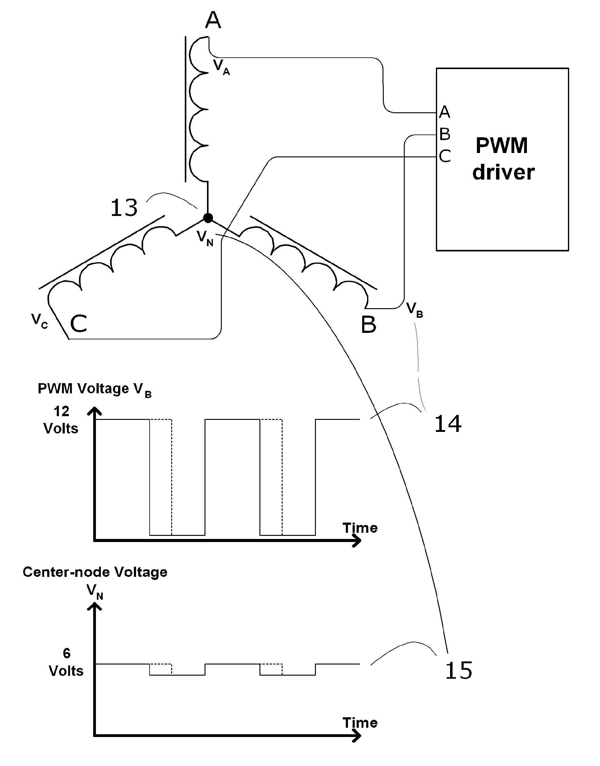
[0062] The present invention measures motor winding inductance using the AC component of the pulse-width modulated motor drive current as a measurement stimulus, and derives the measurement by monitoring AC response at the center-node of a Y-connected winding. The present invention utilizes dynamic changes in that measured inductance to accurately track the position of the motor.
Problems solved by technology
The brushcommutator is still extensively used but suffers from the disadvantages of friction and wear between the brushes and the commutator surfaces, and consequential reliability and maintenance problems are the result.
A commutator also adds complexity and size to the motor.
All of the above methods add extra cost to the system and take up extra space in or near the motor.
In addition, some of the aforementioned methods have accuracy and reliability issues.
A major disadvantage is that this method works only when the rotor is rotating at a reasonable speed, since there is no induced voltage from a stationary magnetic field.
This is acceptable in some applications such as fans and disk drives that use a constant motor rotational speed when operating, but it is unacceptable for many other applications such as robotics and tape drive applications where the motor must remain under close control when being held in a stationary position.
However these methods also add undesirable cost and complexity to the motor.
These techniques tend to require a great deal of complex computation to be done in real-time as the motor runs, tend to have a slow sampling frequency, and may not work when the motor is in a steady-state and not rotating.
Driving a winding with only part of the available voltage results in high losses in the driver circuitry.
Unfortunately this current ripple is small and the signal-to-noise ratio of this measurement is poor, which degrades the accuracy of this position-measurement method.
Method used
Image
Click on the blue label to locate the original text in one second.
Reading with bidirectional positioning of images and text.
Examples
Embodiment Construction
of the Present Invnetion
[0082]FIG. 7 is a schematicblock diagram for one example embodiment of the present invention. The following description of an embodiment of the present invention is given only as an example implementation which has been shown to work. Many other embodiments (not shown) that are within the scope of the present invention are possible. The present invention is therefore not limited by the description of the following embodiment, but only by its claims.
[0083] The implementation as shown in FIG. 7 is based around a C8051 microcontroller 20 made by Silicon Laboratories. This microcontroller is a general purposeembedded controller which includes EEPROM and RAM memory, Pulse-Width Modulation (PWM) controllers, several parallel I / O bits, provision for communication with other processors, Analog-to-Digital (A / D) converter, and other internal peripherals. Many of these internal features proved useful in this design. The C8051 controls power drivers 21, which switch d...
PUM
Abstract
An electronic system utilizing dynamic inductance changes in the windings of an electric motor to measure and monitor mechanical position. The method employs the AC component of the Pulse-Width Modulation (PWM) which is commonly used to drive motor windings without the need for injected AC signals or external position sensors. When a winding of the motor is driven with such an AC signal, the winding inductances form a voltage divider across the center node of a Y-connected motor. Inductance changes in the windings occur as the poles of the rotor pass by the poles of the stator. Considering the PWM drive as an AC stimulus, the voltage response at the center node varies with these inductance changes in the legs on either side; this amplitude variation corresponds to a measurement of rotational position. These measurements provide position / velocity feedback to a servo controller as long as current runs through a motor winding. This position sensing also applies to sensorless control of commutation in brushless DC and switched-reluctance motors.
Description
FIELD OF THE INVENTION [0001] This invention relates to control of polyphase electric motors, specifically to measurement of the rotor position without need for external position sensors. REFERENCES CITED [0002] U.S. Pat. No. 3,931,553 (January 1976) to Stich, et al. [0003] U.S. Pat. No. 4,027,212 (May 1977) to Studer [0004] U.S. Pat. No. 4,092,572 (May 1978) to Murata [0005] U.S. Pat. No. 4,495,450 (January 1985) to Tokizaki, et al [0006] U.S. Pat. No. 4,654,566 (March 1987) to Erdman [0007] U.S. Pat. No. 4,758,768 (July 1988) to Hendricks, et al [0008] U.S. Pat. No. 4,882,524 (November 1989) to Lee [0009] U.S. Pat. No. 5,191,270 (March 1993) to McCormack [0010] U.S. Pat. No. 5,192,900 (March 1993) to Ueki [0011] U.S. Pat. No. 5,304,902 (April 1994) to Ueki [0012] U.S. Pat. No. 5,327,053 (July 1994) to Mann, et al [0013] U.S. Pat. No. 5,350,987 (September 1994) to Ueki [0014] U.S. Pat. No. 5,725,125 (May 1998) to Weiss [0015] U.S. Pat. No. 5,821,713 (October 1998) to Holling, et al...
Claims
Application Information
Patent Timeline
Application Date:The date an application was filed.
Publication Date:The date a patent or application was officially published.
First Publication Date:The earliest publication date of a patent with the same application number.
Issue Date:Publication date of the patent grant document.
PCT Entry Date:The Entry date of PCT National Phase.
Estimated Expiry Date:The statutory expiry date of a patent right according to the Patent Law, and it is the longest term of protection that the patent right can achieve without the termination of the patent right due to other reasons(Term extension factor has been taken into account ).
Invalid Date:Actual expiry date is based on effective date or publication date of legal transaction data of invalid patent.

