Acquisition, pointing, and tracking architecture for laser communication

a laser communication and acquisition technology, applied in the field of acquisition, pointing, and tracking schemes, can solve the problems of reducing the maximum operating range of the system, reducing the signal power at the receiver, and difficult initial acquisition of a remote terminal, so as to reduce the sensitivity to solar radiation and glint.

Active Publication Date: 2007-02-08
PERATON INC
View PDF8 Cites 184 Cited by
  • Summary
  • Abstract
  • Description
  • Claims
  • Application Information

AI Technical Summary

Benefits of technology

[0010] Each free-space laser communication terminal includes a gimbal system on which is mounted: a beacon aperture assembly for transmitting the beacon laser beams; a data aperture such as a telescope for transmitting and receiving the data laser beams and for receiving the beacon laser beams; a steering mirror for controlling an angle at which laser beams are transmitted and received by the data aperture; and a position sensor detector for detecting a direction of beacon laser beams received by the data aperture. Based on feedback from the position sensor detector, a controller controls the positioning of the gimbal system to effect coarse steering of the beacon aperture assembly and the data aperture toward the far-end terminal and controls the positioning of the steering mirror to effect fine steering of the data aperture.
[0011] The beacon laser beams can be modulated on and off such that they are essentially “chopped” laser beams. In this manner, all of the laser communication terminals can transmit and receive beacon laser beams at the same wavelength, using different chopping frequencies to identify and distinguish the terminals. Using a chopped beacon laser signal has the added advantage that the position sensor detector, such as a quad cell detector, can be AC coupled, which reduces sensitivity to solar radiation and glint.

Problems solved by technology

While free-space laser communication systems offer the potential to transmit data at very high data rates over long distances, developing practical systems that operate reliably in moving platform environments (e.g., airborne, space, and ground vehicles) presents unique challenges.
By using a portion of the received data laser beam for position detection, only the remaining portion of the received data laser beam is available for reception of the data, thereby reducing the signal power at the receiver and reducing the maximum operating range of the system.
Given the limited angular extent of the data laser beam, initial acquisition of a remote terminal is difficult with the data laser beam.
Likewise, once a communication link has been established between terminals, it may be difficult for the terminals to continuously track each other using narrow data laser beams, since either terminal can fairly quickly move out of the beam when the relative angular direction of the terminals is changing rapidly.
Additionally, laser tracking schemes can be susceptible to glint and solar radiation, and the track of a moving terminal may be lost if the terminal's line of sight approaches the line of sight of the sun or if persistent glint is present.

Method used


Image

  • Acquisition, pointing, and tracking architecture for laser communication
  • Acquisition, pointing, and tracking architecture for laser communication
  • Acquisition, pointing, and tracking architecture for laser communication

Examples


Embodiment Construction

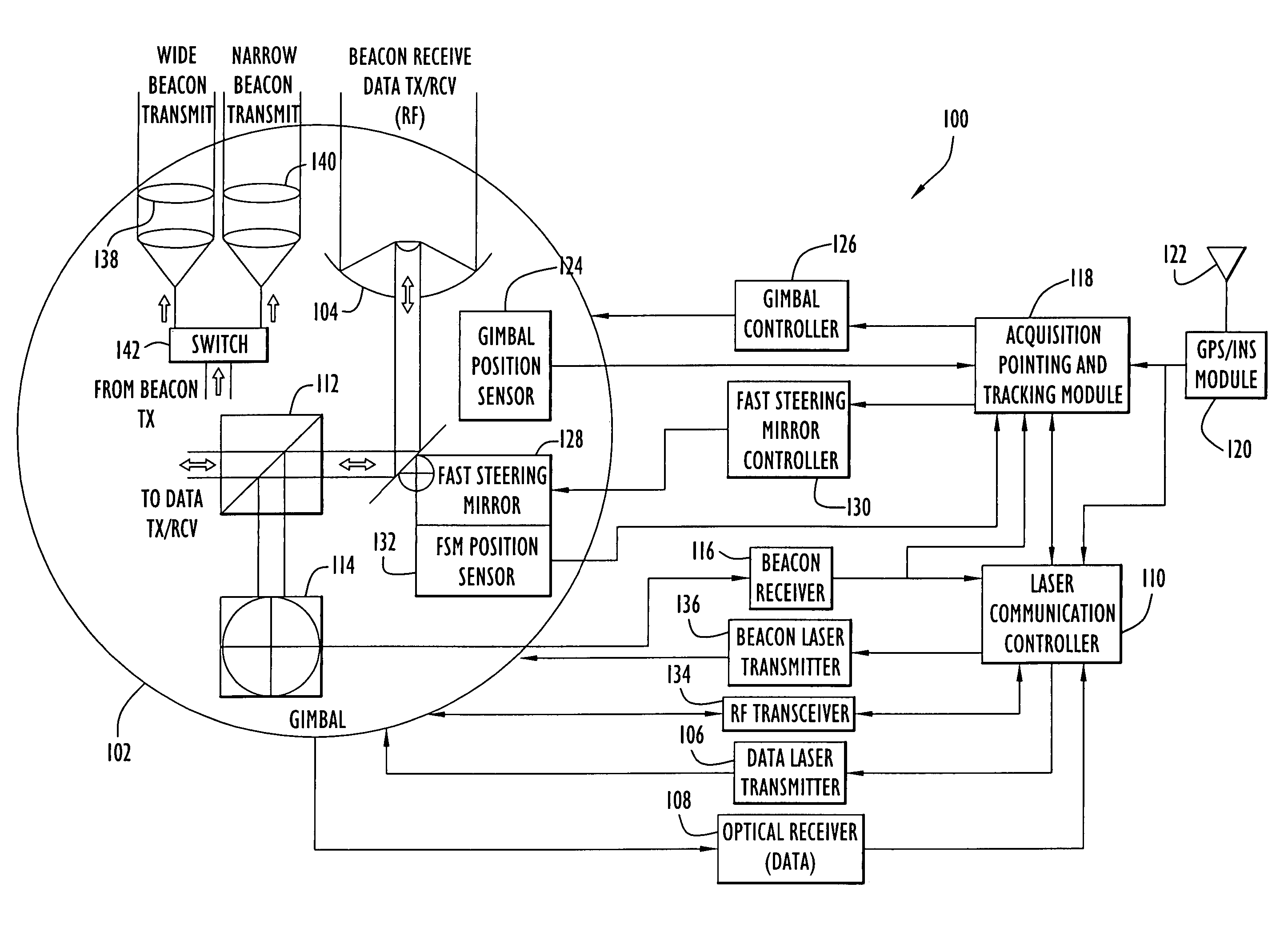
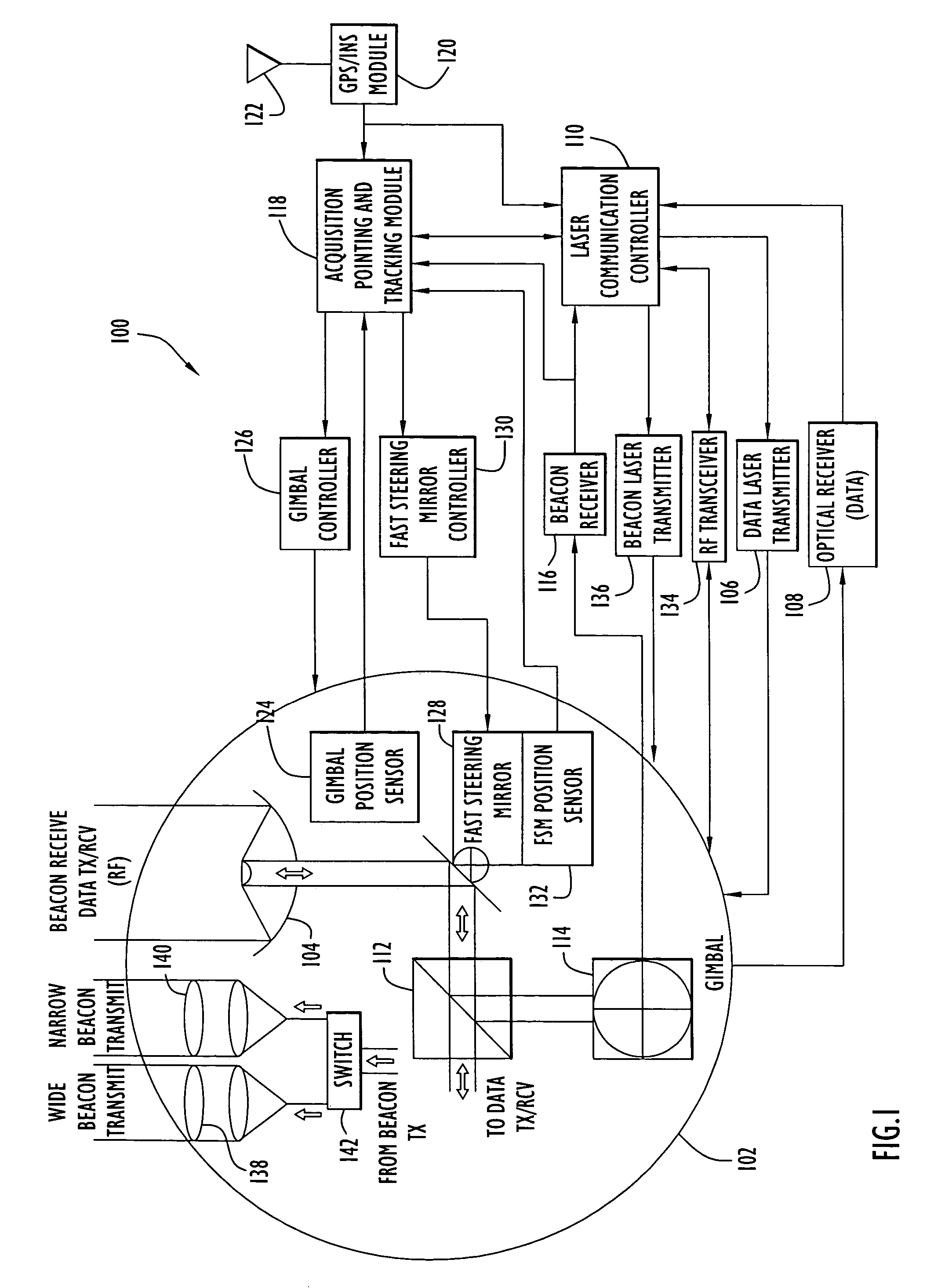
[0017] The following detailed explanations of FIGS. 1-4 and of the preferred embodiments reveal the methods and apparatus of the present invention. FIG. 1 illustrates the system architecture for a laser communication terminal 100 employing an acquisition, pointing, and tracking scheme according to an exemplary embodiment of the present invention. The architecture depicted in FIG. 1 is a conceptual diagram illustrating major functional units, and does not necessarily illustrate physical relationships.

[0018] Laser communication terminal 100 is designed to operate in a laser communication system with moving platforms, where the relative positions of terminals change over time. The system can include, for example, terminals mounted on airborne platforms, satellites, ships, watercraft, or ground vehicles, as well as stationary terminals that communicate with terminals mounted on moving platforms (e.g., combinations of air-to-air and air-to-ground links). The system can include any numbe...


PUM


Abstract

A technique for acquiring and tracking terminals in a free-space laser communication system involves exchanging beacon laser beams between the terminals to acquire and then track the terminals such that data laser beams exchanged by the terminals for communication are steered based on feedback from detection of the beacon laser beams. The beacon laser beams used for acquisition have a greater beam divergence than those used for tracking. Gimbals provide coarse steering of the data laser beams, and steering mirrors provide fine steering. GPS position data exchanged via an RF link can be used for initial pointing of the beacon laser beams for acquisition. The beacon laser beams can be chopped such that all terminals can use the same beacon wavelength and are distinguished by using different chopping frequencies. By detecting a chopped signal, the position sensor detector can be AC coupled to reduce sensitivity to solar radiation and glint.

Description

GOVERNMENT LICENSE RIGHTS [0001] The U.S. Government may have a paid-up license in this invention and the right in limited circumstances to require the patent owner to license others on reasonable terms as provided for by the terms of contract No. F33615-01-D-1849.BACKGROUND OF THE INVENTION [0002] 1. Field of the Invention [0003] The present invention relates to an acquisition, pointing, and tracking scheme useful in a laser communication system. [0004] 2. Description of the Related Art [0005] While free-space laser communication systems offer the potential to transmit data at very high data rates over long distances, developing practical systems that operate reliably in moving platform environments (e.g., airborne, space, and ground vehicles) presents unique challenges. Due to the changing positions of moving platforms, acquisition schemes and precise beam pointing and tracking capabilities are required to operate in these environments. Particularly with airborne platforms, where ...

Claims


Application Information

Patent Timeline
Patent Type & Authority Applications(United States)
IPC IPC(8): H04B10/00H04B10/118
CPCH04B10/1127H04B10/1123H04B7/18506
Inventor CUNNINGHAM, JAMESGRINCH, DEANFISHER, DONALD
Owner PERATON INC
Why Eureka
Try Eureka