System and method for creating a focus-exposure model of a lithography process

a focus-exposure model and lithography technology, applied in the field of optical lithography, can solve the problems of increasing the difficulty of maintaining adequate process margins in the lithography process, becoming impossible to simply determine the mask pattern, and unable to look at the mask pattern, so as to achieve the effect of improving the accuracy and robustness of simulation

Active Publication Date: 2007-02-08
ASML NETHERLANDS BV
View PDF13 Cites 345 Cited by
  • Summary
  • Abstract
  • Description
  • Claims
  • Application Information

AI Technical Summary

Benefits of technology

[0021] A system and a method for creating a focus-exposure model are introduced for the calibration of lithography simulation models. The system and the method utilize calibration data along multiple dimensions of parameter variations, in particular within an exposure-defocus process window space. The sy

Problems solved by technology

This trend towards “sub-wavelength lithography” has resulted in increasing difficulty in maintaining adequate process margins in the lithography process.
In fact, it is becoming impossible to look at the mask pattern and simply determine what the final wafer pattern is supposed to look like.
This greatly increases the difficulty in verifying that the design data is correct before the mask is made and wafers exposed, as well as verifying that the RETs have been applied correctly and that the mask meets its target specifications.
The cost of manufacturing advanced mask sets is steadily increasing.
Currently, the cost has already exceeded one million dollars per mask set for an advanced device.
However, such software often runs extremely slow and hence is limited to extremely small areas of a chip design (on the order of a few square microns).
Even for the “fast” simulation that uses empirical models, a simulation at a full-chip level often requires tens of hours to many days.
These limitations and imperfections include, e.g., corner rounding due to finite spatial resolution of the mask writing tool, possible line-width biases or offsets, and proximity effects similar to the effects experienced in projection onto the wafer substrate.
On the other hand, all “fast” simulatio

Method used


Image

  • System and method for creating a focus-exposure model of a lithography process
  • System and method for creating a focus-exposure model of a lithography process
  • System and method for creating a focus-exposure model of a lithography process

Examples


Embodiment Construction

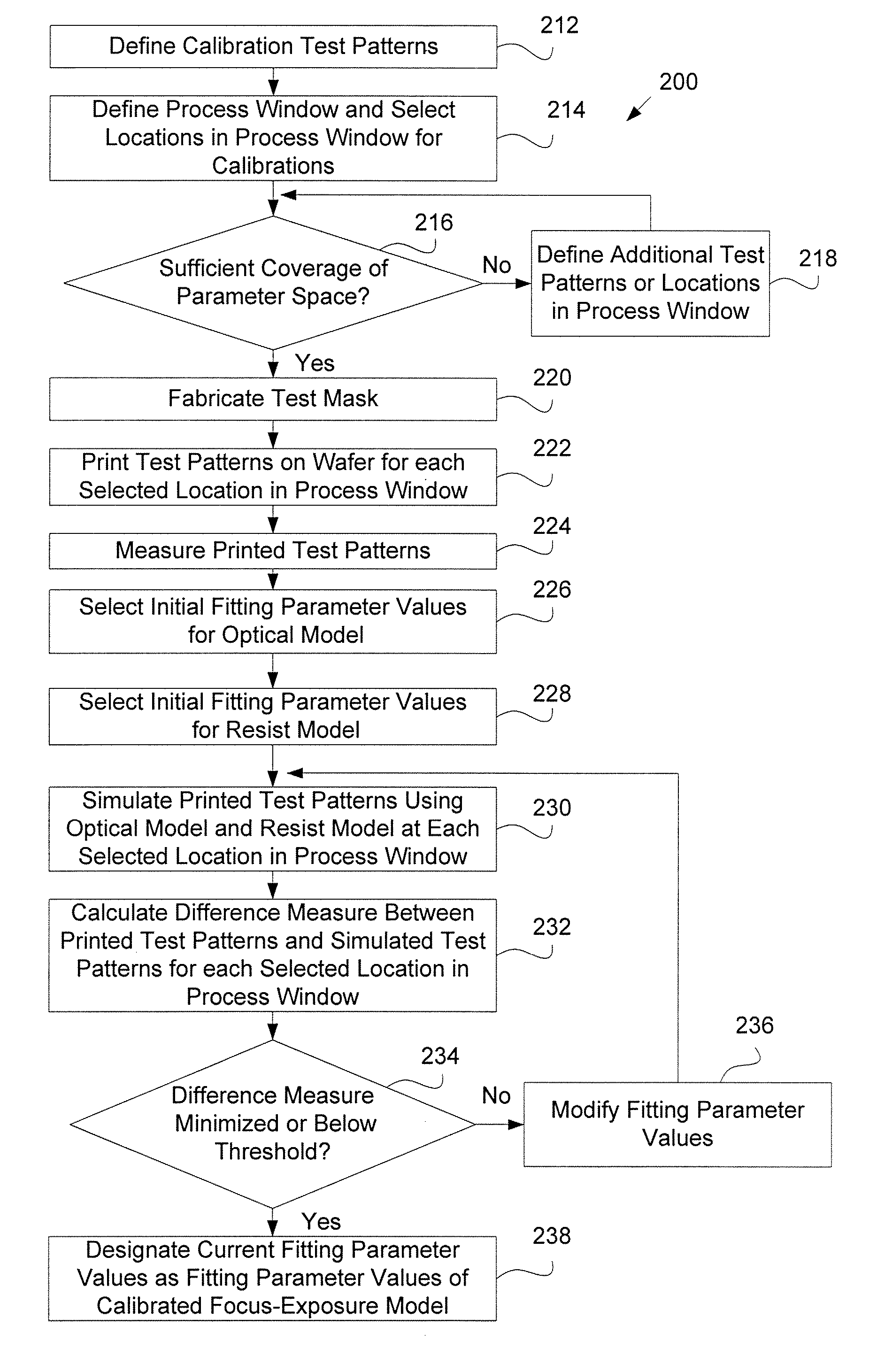
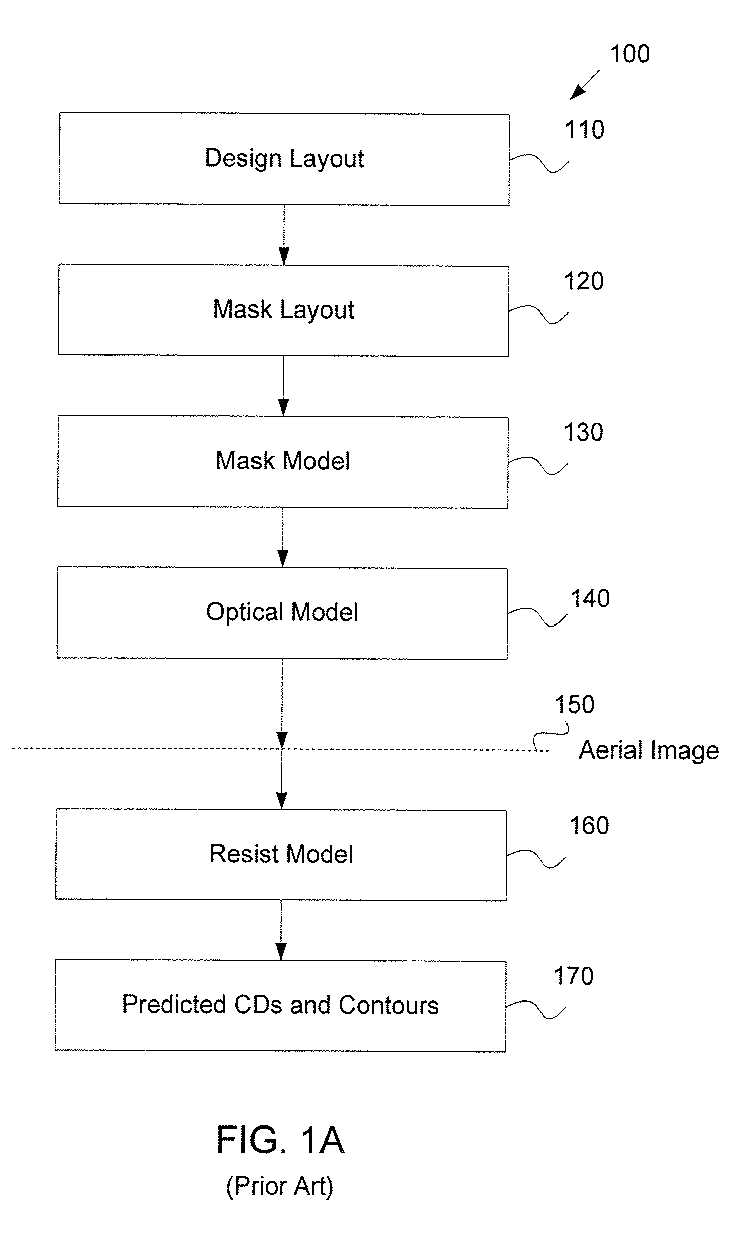
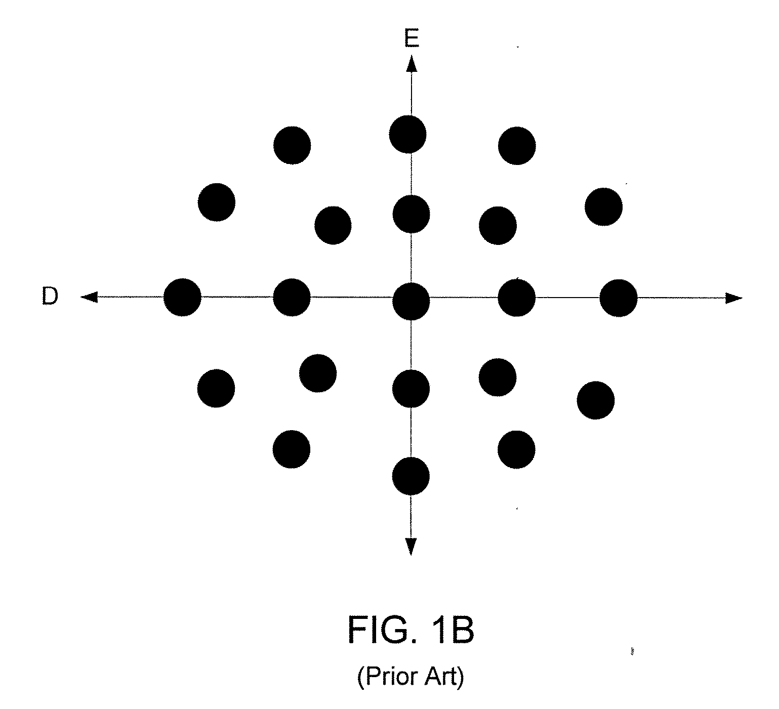
[0036] Disclosed are a system and a method based upon model creation and model calibration, which rely upon incorporating data points not only at nominal condition at the center of the process window but also at different locations within the process window at some distance from the center. At minimum, calibration data is collected while varying at least one process parameter (for example, the defocus parameter), and all collected calibration data with the different values of the varied process parameter are utilized for calibration of the model's fitting parameters. The model of the lithography process includes an optical model module, and may optionally include a resist model module, a mask model module, and other appropriate model modules. The model modules of the model of the lithography process will be referred to herein as models, e.g., the optical model and the resist model, for simplicity.

[0037] In a preferred implementation, calibration data are collected while varying the...


PUM


Abstract

A system and a method for creating a focus-exposure model of a lithography process are disclosed. The system and the method utilize calibration data along multiple dimensions of parameter variations, in particular within an exposure-defocus process window space. The system and the method provide a unified set of model parameter values that result in better accuracy and robustness of simulations at nominal process conditions, as well as the ability to predict lithographic performance at any point continuously throughout a complete process window area without a need for recalibration at different settings. With a smaller number of measurements required than the prior-art multiple-model calibration, the focus-exposure model provides more predictive and more robust model parameter values that can be used at any location in the process window.

Description

CROSS-REFERENCE TO RELATED APPLICATION [0001] This application claims the benefit of U.S. Provisional Patent Application No. 60 / 706,144, entitled “Methodology of Unified, Through-Process Window Lithography Modeling.” The subject matter of this related application is hereby incorporated by reference in its entirety.FIELD OF THE INVENTION [0002] This invention relates generally to optical lithography and more particularly to creating a focus-exposure model of a lithography process. BACKGROUND [0003] The integrated circuit industry has, since its inception, maintained a remarkable growth rate by driving increased device functionality at lower cost. Leading edge devices today provide the computing power of computers that used to occupy entire rooms at a mere fraction of the cost. Many of today's low cost consumer devices include functionality that only a few years ago was unavailable at any cost, such as video cell phones, ultra-portable media players, and wireless or ultra-wideband Int...

Claims


Application Information

Patent Timeline
IPC IPC(8): G03C5/00G03B27/42
CPCG03F7/705G03F7/70641G03F7/70625G03F7/70516
Inventor YE, JUNCAO, YUCHEN, LUOQILIU, HUA-YU
Owner ASML NETHERLANDS BV
Why Eureka
Try Eureka