Control unit, supercharging system, vehicle comprising a supercharging system and method of controlling a supercharging system

a supercharging system and control unit technology, applied in the direction of electric control, combustion engines, machines/engines, etc., can solve the problems of inability to control the compressor very precisely, the maximum power that can be delivered is limited, and the turbocharger will not always be able to provide sufficient compression, etc., to achieve more precise control, reduce communication, and reduce the effect of em

Inactive Publication Date: 2007-02-15
GM GLOBAL TECH OPERATIONS LLC
View PDF12 Cites 23 Cited by
  • Summary
  • Abstract
  • Description
  • Claims
  • Application Information

AI Technical Summary

Benefits of technology

[0019] The arrangement according to the invention enables the control of the compressor with respect to the air pressure, instead of the motor speed of the electric motor driving the compressor. This makes the control more precise and faster than in the prior art.
[0020] At the same time, the distribution of control functions to control units closer to the units being controlled, and communicating with the engine control module, enables the installation of the compressor without major modifications to the engine control module. Thus, the invention provides a flexible compressor unit that can be installed in any type of car without significant modification of the control system already present in the car.
[0021] The invention also reduces the communication between the engine control module and the units associated with the compressor, thus reducing the EMC.
[0022] Prior art solutions to reduce the emission from the engine generally increase the fuel consumption instead. The invention provides a cost efficient solution to this problem in that it enables the reduction of particle emission without increasing the fuel consumption. The feedback from the e-compressor to the control unit also enables monitoring the function of the e-compressor so that any malfunction can be discovered. For efficient catalyst light off, that is, for starting the catalyst as fast as possible, the electrically controlled compressor can be used to supply additional oxygen to the exhaust manifold. The supplied oxygen fuel excessives then combust in order to heat the catalyst after start of the combustion engine. Using the e-compressor to supply this air eliminates the need for a dedicated air pump.

Problems solved by technology

In internal combustion engines, the maximum power that can be delivered is limited by the amount of fuel that can be burned efficiently inside the engine cylinders.
This in turn is limited by the amount of air that is introduced into each cylinder at each cycle.
The energy available to the turbocharger is dependent on the presence of exhaust gases in the outlet from the engine, which means that the turbocharger will not always be able to provide sufficient compression, while the separate supercharger always has sufficient power from the engine or from a separate power source.
This poses certain difficulties, since the resulting pressure from a certain increase in the motor speed varies with the motor speed value, ambient air pressure etc.
Thus, the control of the compressor is not very exact and must be based on trial and error in any given case, that is, if increased compression is required, an increase in motor speed is ordered, the result is evaluated and the motor speed may have to be adjusted again based on the result.
Otherwise, the high temperatures developed in the compressor, along with the high pressure, would compromise the function of the compressor.

Method used


Image

  • Control unit, supercharging system, vehicle comprising a supercharging system and method of controlling a supercharging system
  • Control unit, supercharging system, vehicle comprising a supercharging system and method of controlling a supercharging system
  • Control unit, supercharging system, vehicle comprising a supercharging system and method of controlling a supercharging system

Examples


Embodiment Construction

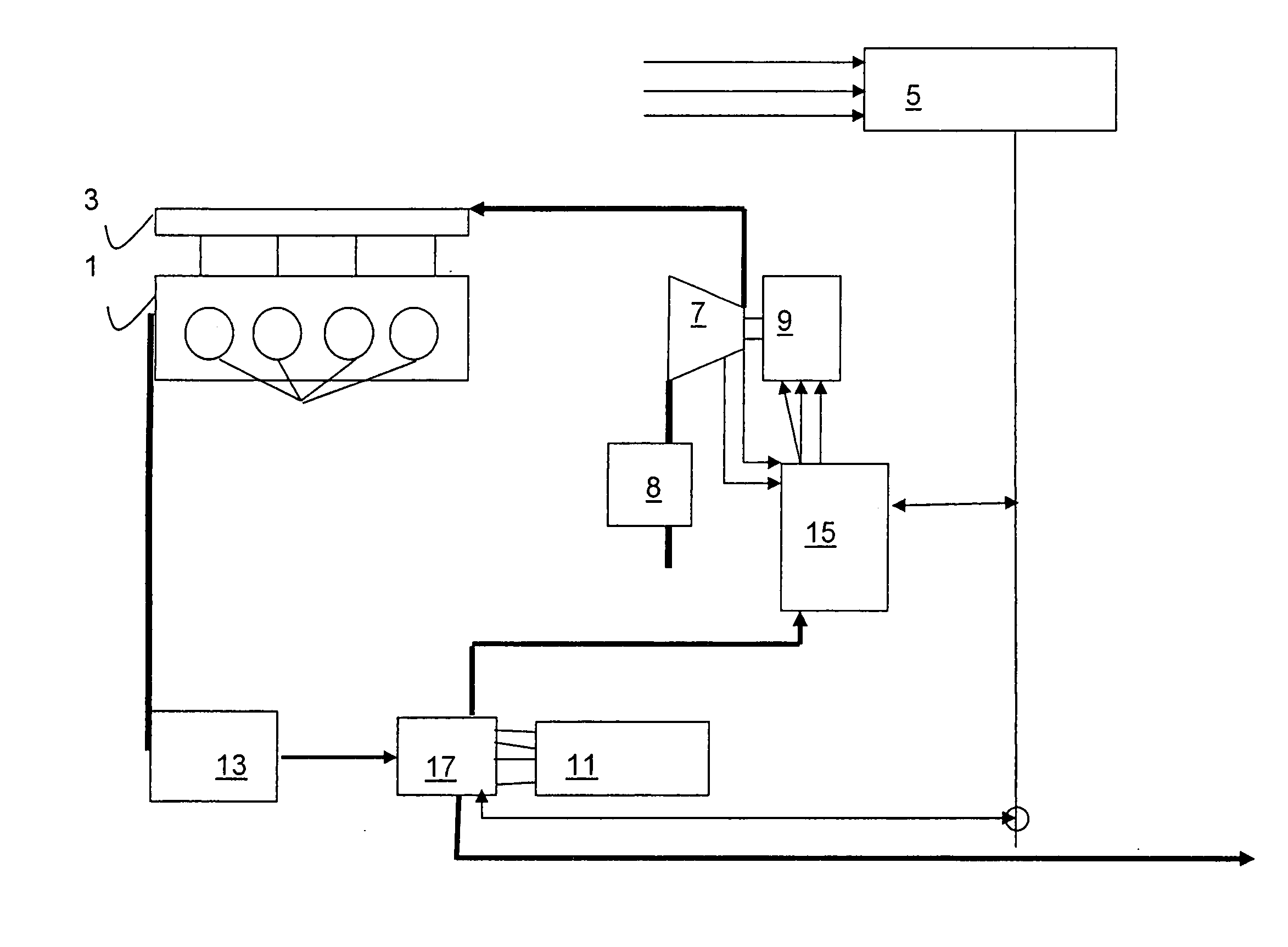
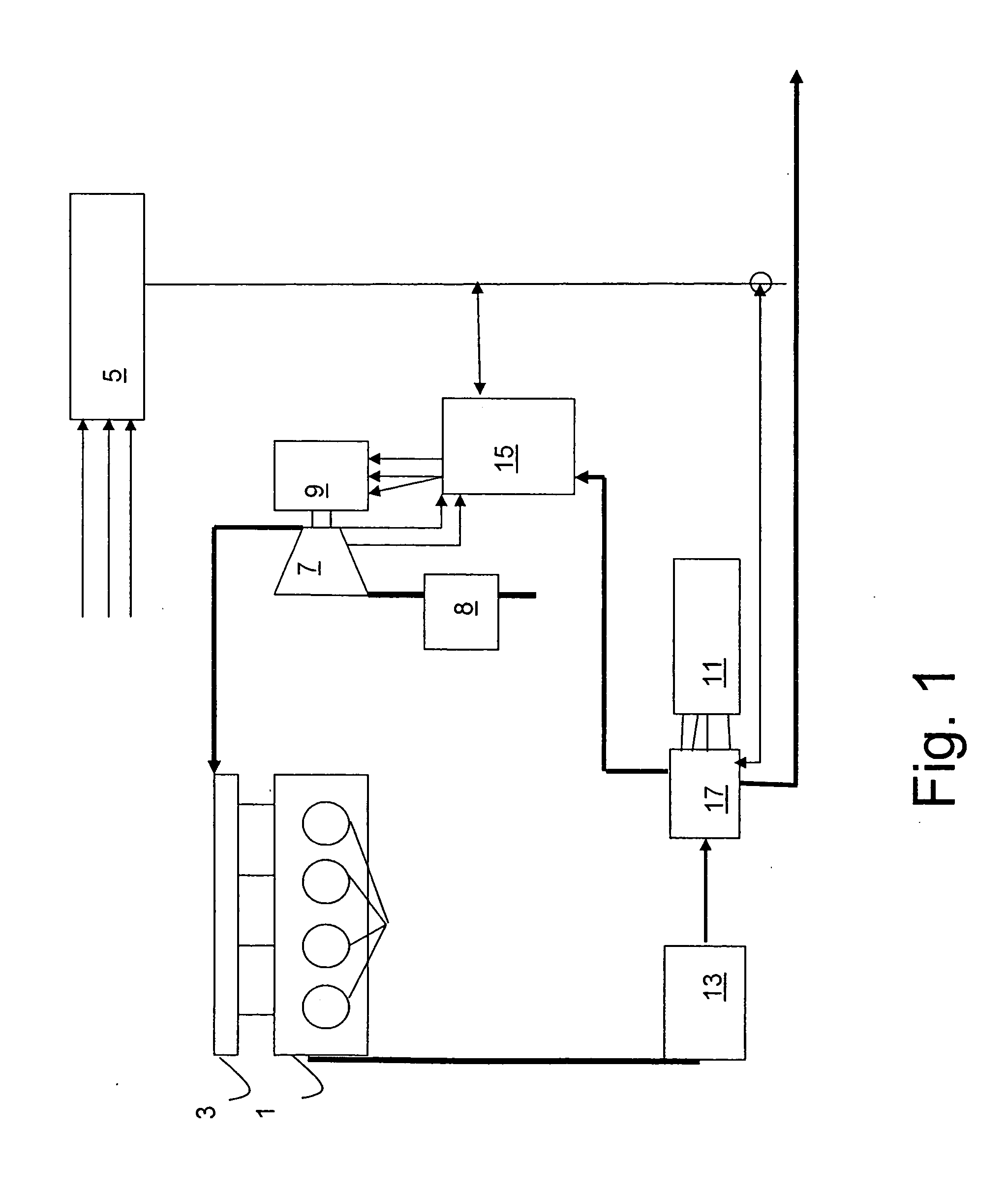
[0036]FIG. 1 illustrates schematically the function of an electrically controlled compressor according to the present invention. An internal combustion engine 1 has air, or air-fuel mixture, delivered to it through an inlet 3, as is common in the art. An engine control unit 5 controls the function of the engine 1. To do this, the engine control unit receives various input signals indicative of engine and vehicle operating parameters, such as the engine speed, and the position of the accelerator pedal. Connected to the engine 1 is an electrically controlled supercharger 7, here referred to as the e-compressor. There is an air inlet to the e-compressor, through an air filter, as is common in the art. The e-compressor 7 is driven by an electric motor 9, which is powered by a battery 11. Preferably, but not necessarily, the battery is charged by a generator 13 driven by the engine 1. The battery can be the same battery that is used for the starting, lighting and ignition requirements of...


PUM


Abstract

A control unit for controlling a supercharging system connected to an internal combustion engine for providing a higher air pressure in the air inlet to the engine, is described, said engine being controlled by an engine control module, said control unit arranged to receive a control signal from the engine control module indicating a desired air inlet pressure to the engine and to receive from the supercharging system a pressure signal representing a current air pressure generated in the supercharging system and to control the function of the supercharging system in dependence of the control signal and the at least one air pressure signal. Other control units, for example, for the batteries, may be added to the system to achieve a distributed control system.

Description

REFERENCE TO RELATED APPLICATION [0001] This application claims the benefit of the filing date of Swedish Patent Application No. SE 0501177-0, filed May 25, 2005, the disclosure of which is hereby incorporated by reference. FIELD OF THE INVENTION [0002] The present invention relates to a control unit for controlling a supercharging system as defined in the preamble of claim 1. It also relates to a supercharging system as defined in the preamble of claim 11, a vehicle as defined in the preamble of claim 25 and a method of controlling a supercharging system according to the preamble of claim 27. BACKGROUND OF THE INVENTION [0003] In internal combustion engines, the maximum power that can be delivered is limited by the amount of fuel that can be burned efficiently inside the engine cylinders. This in turn is limited by the amount of air that is introduced into each cylinder at each cycle. To improve the efficiency of an engine, therefore, the induced air is often compressed. Increasing...

Claims


Application Information

Patent Timeline
Patent Type & Authority Applications(United States)
IPC IPC(8): F02B33/00
CPCF02B33/34F02B37/04F02B37/12Y02T10/144F02D23/02F02D41/0007F02B39/10F05D2260/6022Y02T10/12F02D23/00
Inventor WIJK, JAN-ERIKFREDRIKSSON, CARL
Owner GM GLOBAL TECH OPERATIONS LLC
Why Eureka
Try Eureka