Power generation system

a power generation system and power generation module technology, applied in the direction of electrical equipment, electric vehicles, vehicle components, etc., can solve the problems of large loss of power devices, low utilization rate, and only 90% of the output of solar cells used as output, so as to achieve full utilization rate of power generating modules, reduce noise and harmonic waves, and effectively utilize output

Inactive Publication Date: 2007-02-15
SPHELAR POWER
View PDF56 Cites 39 Cited by
  • Summary
  • Abstract
  • Description
  • Claims
  • Application Information

AI Technical Summary

Benefits of technology

[0013] However, as described above, the DC output voltage can be changed stepwise by simply switching the first, second and third switch means while effectively utilizing the output of all of the power generating modules. Without idling the power generating modules, the utilization rate of the power generating modules is fully improved.
[0014] Although switching the plurality of the first, second and third switch means still needs to be performed, the voltage change due to switching of the switch means is small, and therefore, less noise and harmonic waves are generated in comparison with the conventional PWM method. This allows simplifying the electric circuit structure by decreasing the filter capacity for noise and harmonic wave absorption or electric magnetic field interference. In addition, the switching frequency of the plurality of first, second and third switch means becomes smaller in comparison with the switching element of the inverter circuit of the PWM system, and small switching elements can be used for the plurality of first, second and third switch means, which decrease the switching loss or the switching cost.
[0015] Now, when the power generating module is a solar battery power generating module, the connecting pattern of the first, second and third switch means can be changed to adjust the DC power voltage produced from the power generator according to the output voltage drop of the power generating module when it is cloudy, in the morning or evening, eliminating the use of a boosting chopper, which makes this power generating system versatile and flexible. Then, since electric property such that the output current decreases stepwise when the output voltage is increased in multi-levels, whereas the output current increases in multi-levels when the output voltage is decreased stepwise, is designed by switching the plurality of first, second and third switch means, it can be controlled to operate the system when the power generator is at a maximum power point.
[0016] Alternatively, even when the output voltage property of any of the plurality of solar battery power generating modules is not consistent or the amount of generated power is significantly decreased when buildings and the like partially block the solar battery power generating module, the electric storage means connected in parallel to the power generating modules having decreased power voltage outputs a specified voltage DC power to the positive / negative buses to compensate for the output voltage drop for the power generating modules, to level the output power to improve the DC voltage-DC current property of the power generating modules. Furthermore, even when the plurality of power generating modules are generating the DC power as it becomes at night and no sunlight is available, a specified voltage DC power is produced from the electric storage means in electric storage stage to the positive / negative buses, so that the power generation property is significantly improved without limiting the power generation time. These are the advantages of the power generating system of the present invention.

Problems solved by technology

However, regarding the technology controlling the inverter circuit using the above PWM method, there is a problem that approximately only 90% of the output of solar battery is utilized as the output of the solar battery, and needs to be intermittently shut off to convert to AC power.
In addition, there is another problem of having a large loss in power devices, such as an inverter circuit and switching elements due to the large number of switching frequencies involving significant voltage changes.
However, there is the problem that the rate of utilization becomes significantly lower since all of the four solar batteries are used only for a short time to generate a peak voltage and one or a plurality of solar batteries are in the idle stage most of the time.
Furthermore, there is another problem that the DC voltage is not generated from any of the four sets of the solar batteries 110 during the nights when sunlight is not available, therefore, the power generation time by the solar battery 110 is limited to affecting the performance of power generation by the power generation system.
Since each single cell generates approximately 0.6-0.7V DC power, and there is the same problem as the solar electric generating system in a way which utilizes technology to provide DC power generated from a power generating system to an AC system by having the power generating system cooperate with a home single phase AC system.

Method used


Image

  • Power generation system
  • Power generation system
  • Power generation system

Examples


Embodiment Construction

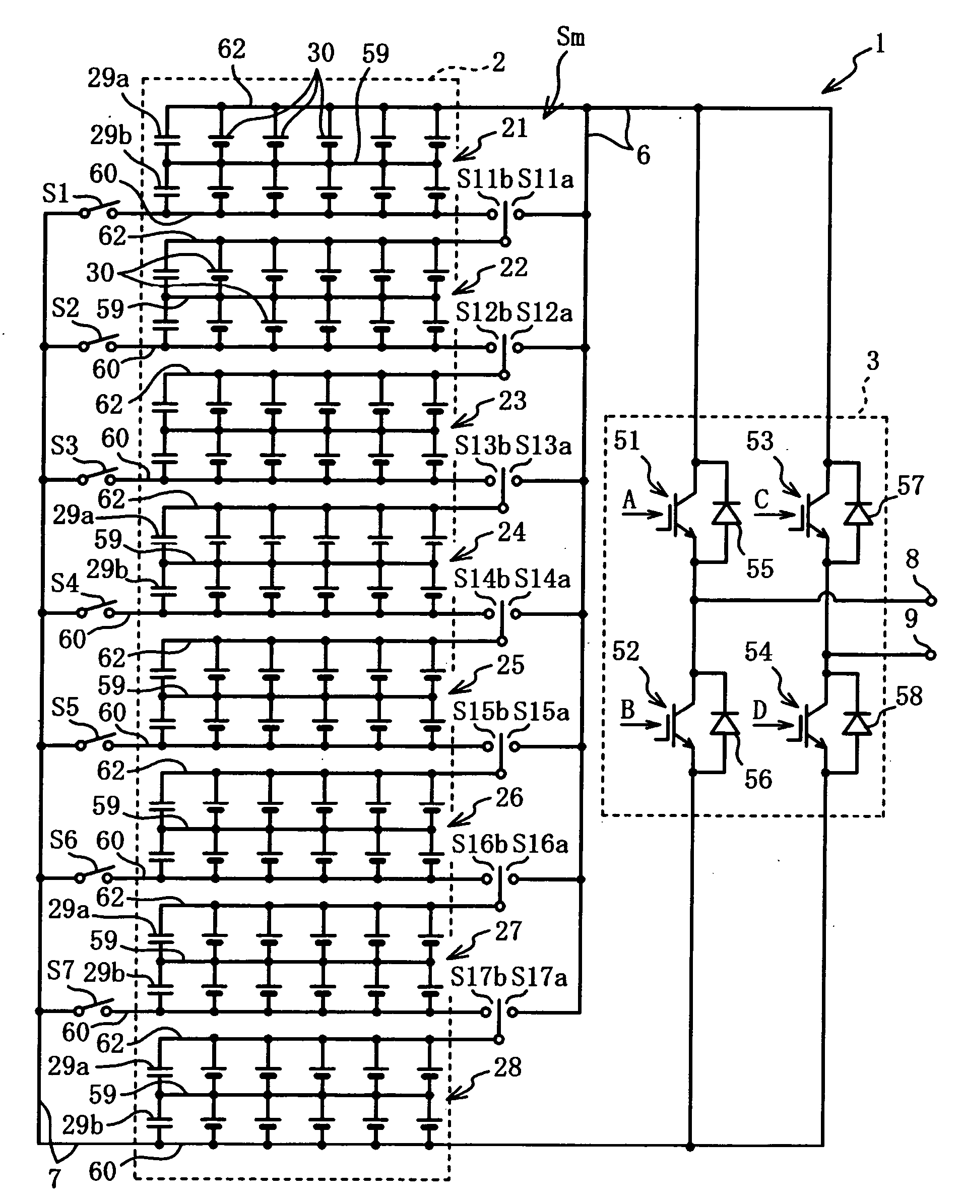
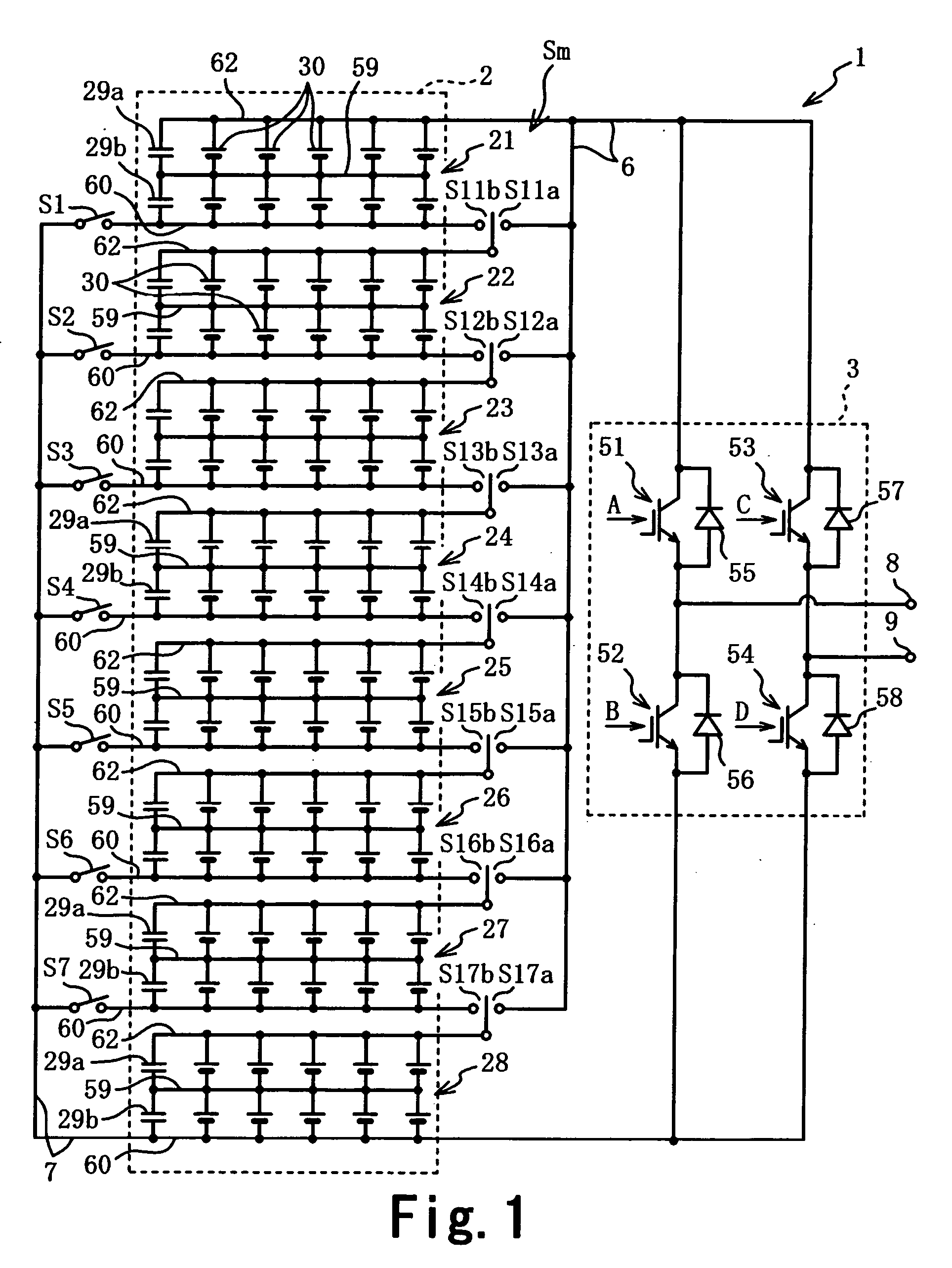
[0053] A preferred embodiment to implement a power generating system of the present invention will be described hereinafter.

[0054] As shown in FIG. 1-FIG. 7, the power generating system 1 is comprising a power generator 2 electrically generating DC power, an inverter circuit 3 for converting DC power generated by the power generator 2 into AC power to output the single phase AC system, a switching mechanism Sm to switch the DC power voltage of the power generator 2 in multi-levels, a control device 4 controlling these switch mechanism Sm and switching elements 51-54 of the inverter circuit 3, and a voltage detector 5 to enter the control device 4 after detecting the single phase AC system voltage.

[0055] For the sake of simplicity of descriptions, the power generator 2 in accordance with the present embodiment is comprising 8 power generating modules 21-28, the electric double layer capacitors 29a for electric storage each of which is connected to positive electrode 62 and parallel...


PUM

PropertyMeasurementUnit
voltageaaaaaaaaaa
voltageaaaaaaaaaa
voltageaaaaaaaaaa

Abstract

A power generating system 1 comprises a power generator 2 generating DC power, and an inverter circuit 3 for converting DC power into AC power; the power generator 2 comprises a plurality of power generating modules 21-28 each comprising a plurality of power generating units 30 and at least one electric storage means connected to each of the plurality of power generating modules 21-28. A plurality of first switch means S11a-17a connect / disconnect each of the positive electrodes 62 of the plurality of power generating modules 22-28 to / from a positive bus 6, a plurality of second switch means S11b-17b connect / disconnect each of the positive electrodes 62 of the plurality of power generating modules 22-28 to / from the negative electrodes 60 of the power generating modules 21-27 contiguous to the one side, a plurality of third switch means S1-S7 connect / disconnect each of the negative electrodes 60 of the plurality of power generating modules 21-27 to / from a negative bus 7, and the DC output voltage can be increased / decreased stepwise by switching the switch means S1-S7, S11a-17a and S11b-S17b.

Description

TECHNICAL FIELD [0001] The present invention relates to a power generating system generating AC power via an inverter circuit from DC power generated from solar batteries or fuel cells to improve a switching mechanism for switching the voltage of DC power in multi-steps, and electric storage and power generation performance. BACKGROUND OF THE RELATED ART [0002] Thanks to the recent gradual decrease in the production cost of solar batteries used in solar electric generating systems, many consumers utilize solar electric generating systems at home, although many of the home solar electric generating systems are cooperation type systems connected to a commercial single phase AC system supplied to residential areas. The solar battery of home solar power electric generating systems is connected in series-parallel to several dozen power generating modules with small kW output. The cooperation type solar electric generation systems require converting DC power into AC power via an inverter ...

Claims


Application Information

Patent Timeline
Patent Type & Authority Applications(United States)
IPC IPC(8): H01L31/042H01M8/00H02N6/00H01L31/04H02J1/00H02J3/38H02J5/00H02J7/35H02M7/48
CPCH02J7/35H02M7/483H02J3/383Y02E10/58Y02E10/563Y02E10/566H02J3/385H02J2300/30H02J2300/26H02J2300/24H02J3/381Y02E10/56H02J3/466
Inventor NAKATA, JOSUKE
Owner SPHELAR POWER
Why Eureka
Try Eureka