White organic light-emitting diode

Active Publication Date: 2007-02-15
AU OPTRONICS CORP
View PDF10 Cites 37 Cited by
  • Summary
  • Abstract
  • Description
  • Claims
  • Application Information

AI Technical Summary

Benefits of technology

[0008] In another aspect, the present invention provides a WOLED, which can be easily fabricated and can decrease color shift of its emitting l

Problems solved by technology

Because of this increasing red shift, controlling

Method used


Image

  • White organic light-emitting diode
  • White organic light-emitting diode
  • White organic light-emitting diode

Examples


Embodiment Construction

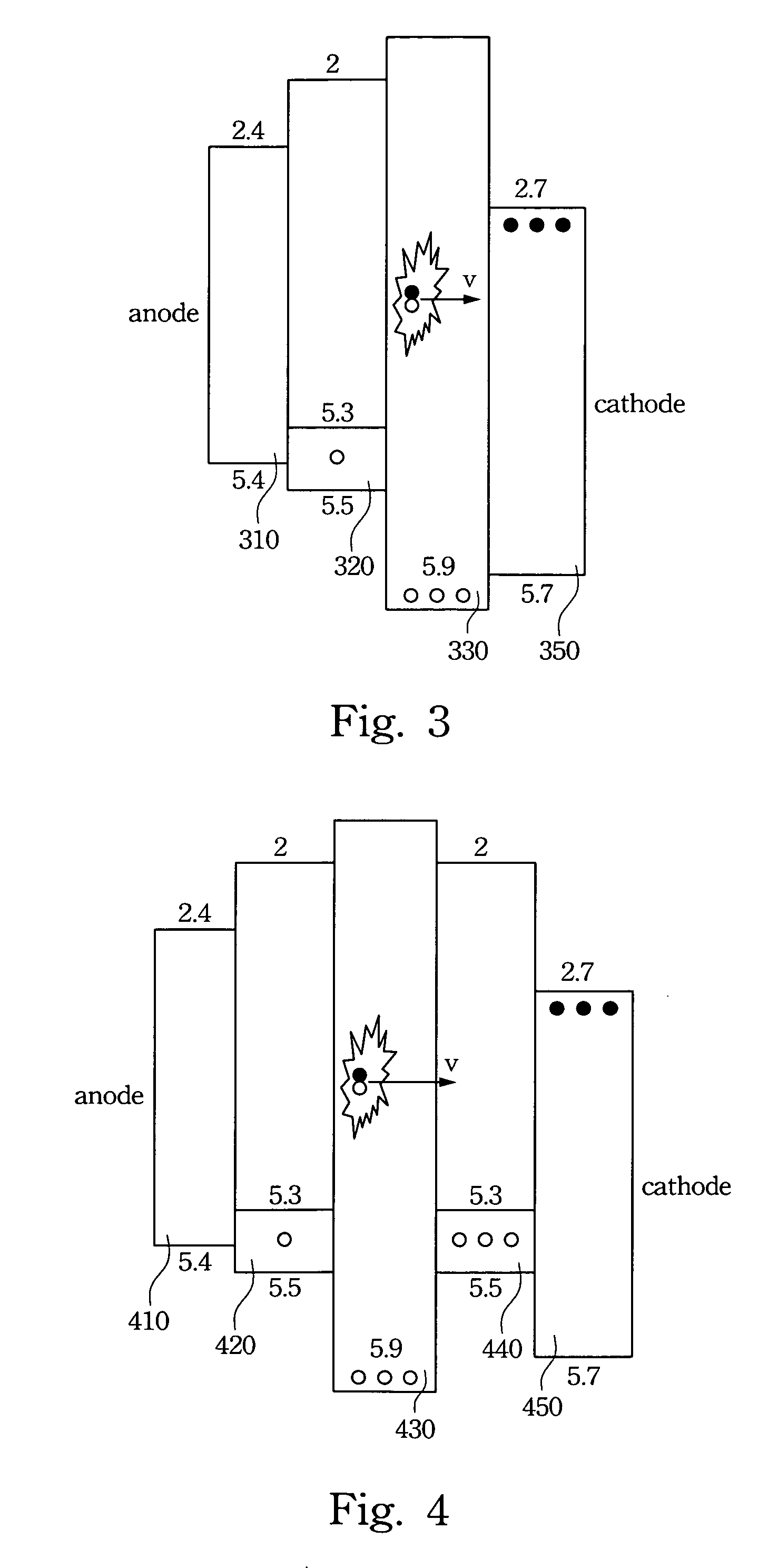
[0018] This invention provides a white organic light-emitting diode (WOLED). Two luminescent layers are arranged on both sides of multiple luminescent layers to resolve the color shift of light emitting from the WOLED when the applied operating voltage varies.

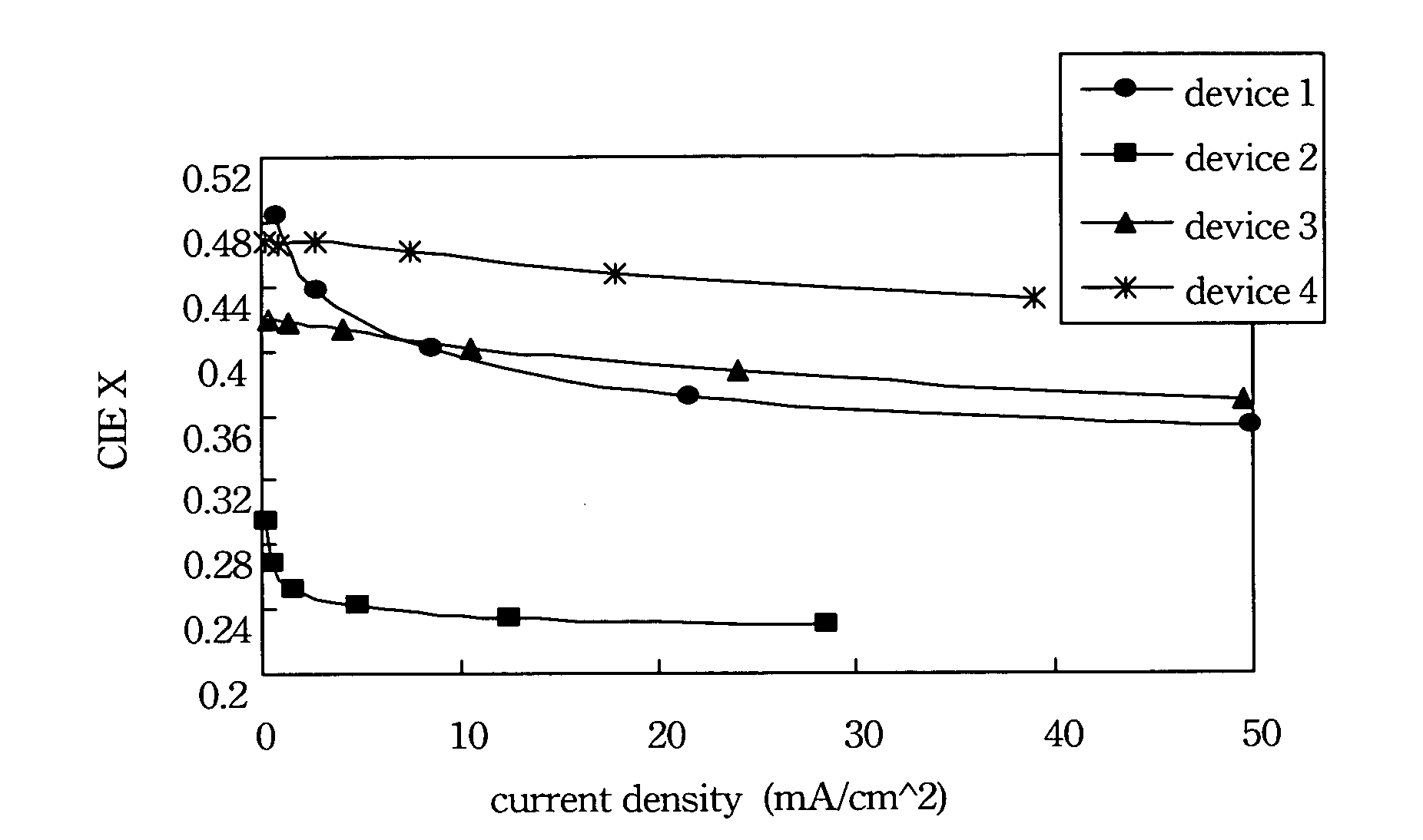
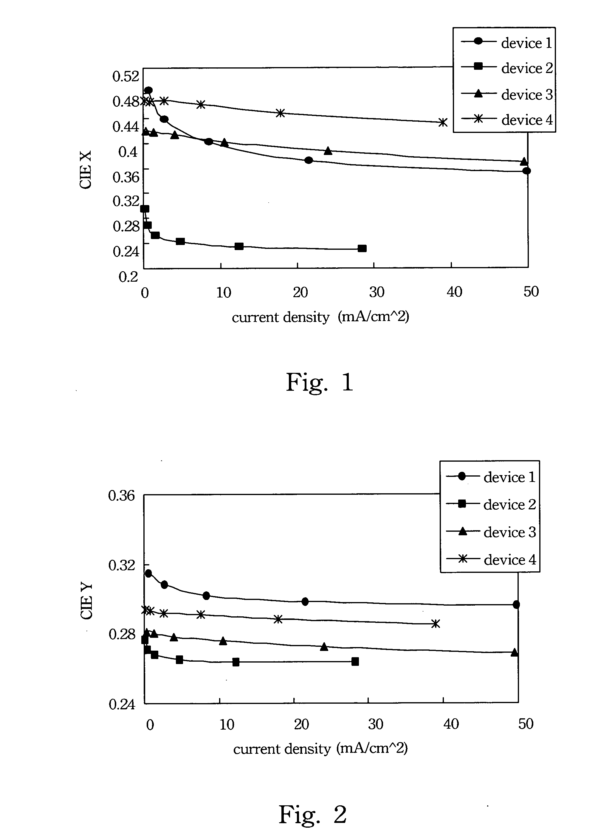
[0019] The chromaticity coordinates (x, y) of standard white defined by Commission International d'Eclairage (CIE) is (0.33, 0.33). However, many other various white colors, such as cold white, warm white, sunlight white, or purple white, are still possible. Therefore, the chromaticity values of white color can vary within a broad range. However for white light generated by an ideal WOLED, the variation of x or y values in CIE coordinates is better when smaller than 0.04.

[0020] In preferred embodiments of this invention, four WOLEDs are produced. All layers are the same in the four WOLEDs except for multiple luminescent layers. The layers of four WOLEDs are sequentially an anode (Al, 1500 Å), an electron injection layer (LiF,...


PUM

PropertyMeasurementUnit
Fractionaaaaaaaaaa
Fractionaaaaaaaaaa
Fractionaaaaaaaaaa

Abstract

A white organic light-emitting diode includes two symmetric emission layers and a middle emission layer. The two symmetric emission layers emit a first color light with approximately the same frequency components. The middle emission layer is located between the two symmetric emission layers. The middle emission layer emits a second color light with frequency components different from main frequency components of the first color light. When the voltage applied to the organic light-emitting diode changes and leads to a decrease of luminescent intensity of one of the symmetric emission layers, the other symmetric emission layer automatically increases the luminescent intensity to compensate for the reduced light intensity.

Description

RELATED APPLICATIONS [0001] The present application is based on, and claims priority from, Taiwan Application Serial Number 94127032, filed Aug. 9, 2005, the disclosure of which is hereby incorporated by reference herein in its entirety. BACKGROUND OF THE INVENTION [0002] 1. Field of Invention [0003] The present invention relates to a light-emitting device. More particularly, the present invention relates to an organic light-emitting diode. [0004] 2. Description of Related Art [0005] A white organic light-emitting diode (WOLED) can be made by a single luminescent layer or multiple luminescent layers. However, the color of the emitting light of the same WOLED varies when the applied operating voltage varies. That is, the wavelength of the emitted light is shifted by applying different operating voltages to the WOLED. [0006] The individual layers of a conventional WOLED are a substrate, an anode (ITO), a hole injection layer (PEDOT:PSS, 40 nm), a hole transfer layer (a-NPD, 40 nm), a ...

Claims


Application Information

Patent Timeline
IPC IPC(8): H01L51/00
CPCH01L51/5036H10K50/125
Inventor YANG, CHUN-HUILIN, CHENG-HUNG
Owner AU OPTRONICS CORP
Why Eureka
Try Eureka