Method and system for cleaning

a cleaning method and a technology for cleaning, applied in the direction of cleaning using liquids, traffic signals, roads, etc., can solve the problems of traffic congestion, effective but also dangerous, etc., and achieve the effects of preventing objects from being scratched, reducing environmental load, and improving energy conservation properties

Active Publication Date: 2007-02-15
SANKI ENG CO LTD
View PDF1 Cites 29 Cited by
  • Summary
  • Abstract
  • Description
  • Claims
  • Application Information

AI Technical Summary

Benefits of technology

[0022] As explained above, the present invention comprising steps of stopping a truck mounted with a cleaning agent blaster, a working robot provided with a blast nozzle and a CCD camera at the front end of a manipulator at a specified position in the vicinity of an object to be cleaned, i.e. a surface light or a reflection mirror; recognizing dimensions from positional information through processing by a vehicle-mounted computer based on an image of the object for cleaning taken by the CCD camera, collating and recognizing the image shape of the object with a stored shape; searching positional information of the recognized object accordingly; and blasting a cleaning agent from the blast nozzle mounted on the front end of the manipulator of the working robot toward the object while measuring the extent of cleaning, determining brightness or light intensity of the cleaned object from the data obtained by the CCD camera to perform automatic cleaning. As a result, it can prevent the object from being scratched by the hardness of abrasives, is innocuous to the human body, and environmental loading can be suppressed as it vaporizes at ambient temperature. Furthermore, the energy conservation property can be improved by lowering the injection pressure while an object is cleaned safely, easily, and effectively.
[0023] In addition, according to the invention, an opening cover panel (or a slide floor) is provided at the center of the load bed of a truck having a canopy, from which an automatic cleaning system operates a manipulator of a robot so as to move a blast nozzle to an object. With this structure, (1) when the cover body mounted on the load bed of a truck is partitioned and a pneumatic expansion cornice surrounds the slide floor opening, cleaning can be performed without leakage of carbon dioxide produced when dry ice used as a cleaning agent is decomposed. Furthermore, the opening cover panel is closed and the cornice is folded after cleaning, so that carbonate dioxide gas is sealed within the cover body. As a result, absorption treatment for carbon dioxide gas can be processed as the truck moves. In addition, a surrounding body can be formed easily, and the time spent for the whole cleaning process can be reduced. (2) Even when robot output is great, since a manipulator is operated in such a manner to project from the lower part of the load bed (a place where a person cannot enter), it is unnecessary to provide a protection fence. (3) When blast for cleaning, such as bicarbonate, which can be diffused is used, it is unnecessary to close the load bed with the opening cover panel (a slide floor).

Problems solved by technology

As previously described, when an object of cleaning is a surface light, a runway guide light, or a reflector, the dust has been conventionally cleaned by hand using a scraper, which is effective but also dangerous if a surface light is cleaned while the traffic continues on the street.
On the other hand, if the traffic of the work site is blocked for a long time, it will likely cause traffic congestion.

Method used


Image

  • Method and system for cleaning
  • Method and system for cleaning
  • Method and system for cleaning

Examples


Embodiment Construction

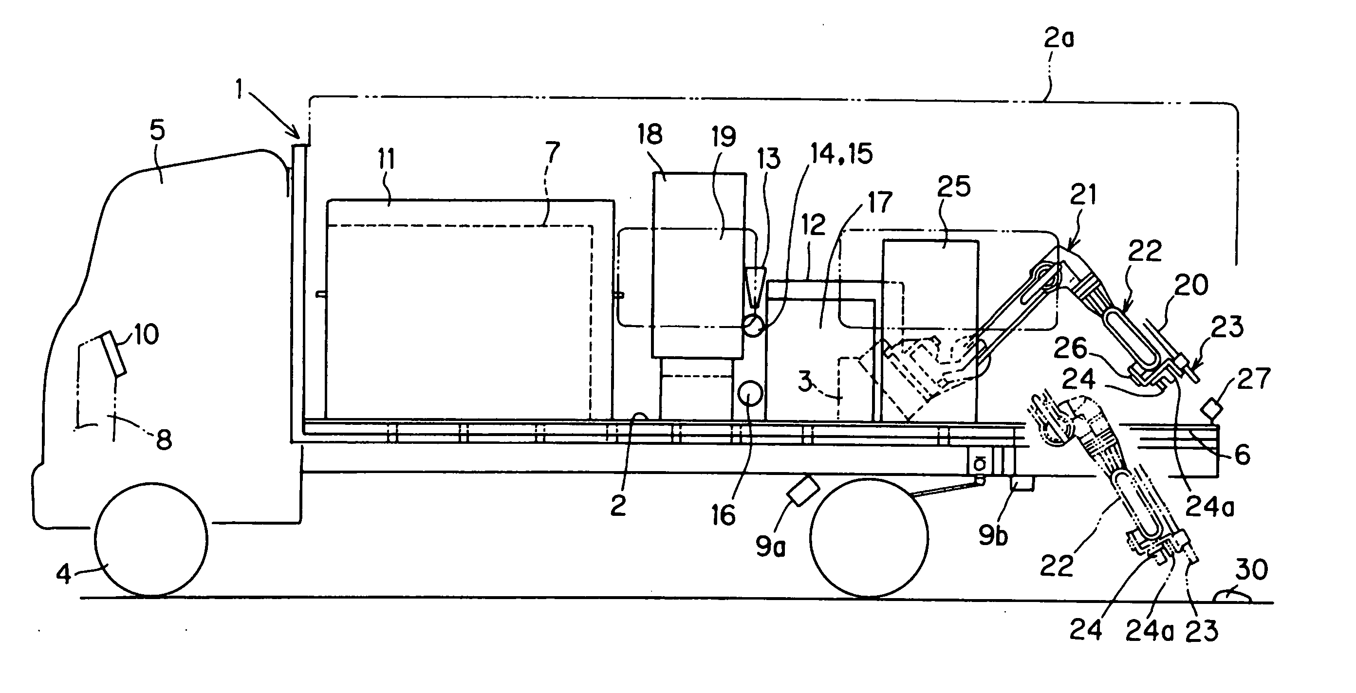
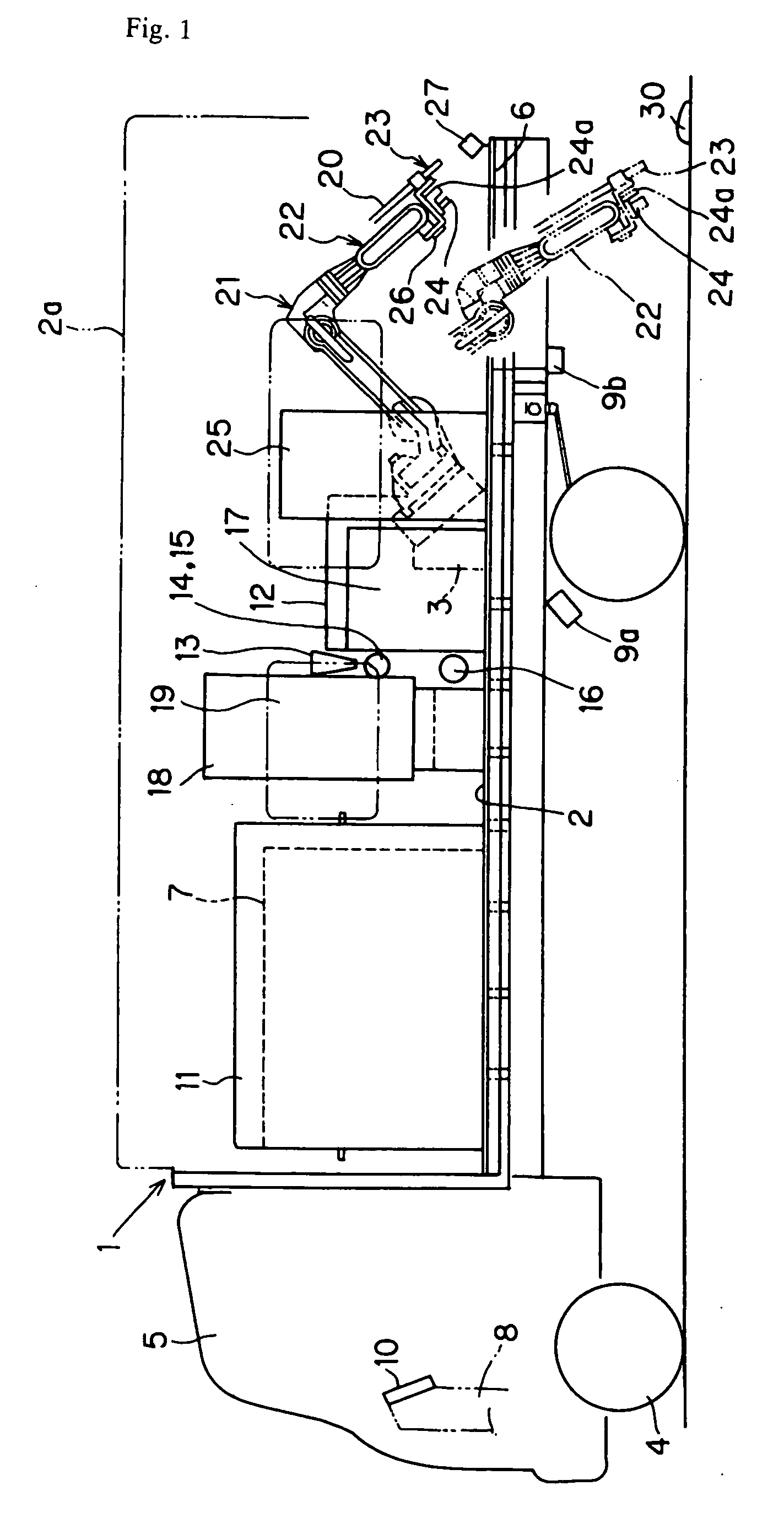
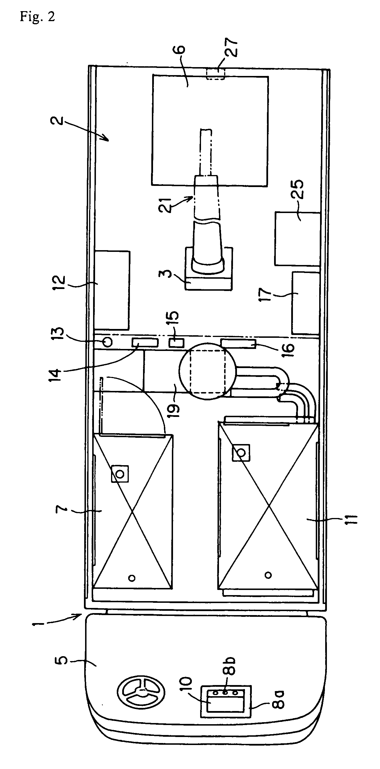
[0028] A generator 7, a compressor 11, an air dryer 12, a filter 13, a blow tank 14, an air delivery valve 15, an ejector 16, a cleaning agent supply controller 17, a tank of dry ice or bicarbonate that is a cleaning agent (a cleaning agent tank) 18, a cleaning agent quantitative feeder 19, a working robot 21., and a robot controller 25 are mounted on the load bed 2 of a truck 1 having a canopy 2a. The working robot 21 shown in the drawings is an articulated robot which is mounted on the slope of a base 3 in an inclined manner. A bracket 26 mounted on a manipulator 22 provided at. the front end of an robot arm in such a manner to be mounted with a blast nozzle 23 connected with a high pressure rubber hose 20 derived from the delivery side of the ejector 16, a CCD camera 24 for detecting a cleaned object (surface light, reflector) 30, and a distance sensor 24a. Furthermore, an approach camera 27 for confirming whether or not the CCD camera 24 is at the stop position is mounted on the...


PUM


Abstract

A method and a system for cleaning the glass surface of an object, such as a surface light, a run way guide light, or a reflector, installed on various pavements or roads, by propelling a cleaning agent from a blast nozzle to the glass surface. The blast nozzle is installed on the front end of an arm of a working robot mounted on a truck. A truck mounted with a cleaning agent blaster and a working robot (21) provided with a blast nozzle (23) and a CCD camera (24) at the forward end of a manipulator is stopped at a specified position in the vicinity of an object to be cleaned, i.e. surface light or a reflection mirror (30). Based on an image of the object taken by the CCD camera (24), dimensions are recognized from distance information through processing by a vehicle-mounted computer, the image shape of the object is collated with a stored shape and recognized, and then positional information of the recognized object is searched. Cleaning agent is propelled from the blast nozzle (23) at the forward end of the manipulator (22) toward the object while measuring the extent of cleaning, brightness or light intensity of the cleaned object is determined by the CCD camera, and automatic cleaning is performed.

Description

BACKGROUND OF THE INVENTION [0001] 1. Field of the Invention [0002] The present invention relates to a method for cleaning the glass surface of a surface light, a runway guide light, or a reflector by blasting a cleaning agent, and a system for carrying out the method. [0003] 2. Prior Art [0004] A surface light, a runway guide light, or a reflector buried or installed on pavement and on road such as a landing strip, a road for tracks, a taxiway or in the vicinity thereof at some distance from each other often cannot perform its predetermined function due to an adhesion of automotive exhaust gas produced by traveling, stopping and starting on a track, adhesion of abrasion dust from tires, debris adhesion of calking compounds for waterproof processing a part of such a surface light, as well as adhesion or fouling of rain water and dust. Although dirt caused by an adhesion of rainwater and dust can be easily removed, it is not easy to completely remove a small dot-like spot from abrasi...

Claims


Application Information

Patent Timeline
Patent Type & Authority Applications(United States)
IPC IPC(8): B24B51/00B24B49/00B08B3/02B08B7/00B08B7/02E01F9/00E01H1/00
CPCB08B3/02E01H1/005B08B7/02
Inventor OHISHI, NAOYUKIKAWAGUCHI, HISAAKI
Owner SANKI ENG CO LTD
Why Eureka
Try Eureka