
Power factor correction rectifier having independent inductive components

Active Publication Date: 2007-02-22
DELTA ELECTRONICS INC
View PDF3 Cites 10 Cited by
  • Summary
  • Abstract
  • Description
  • Claims
  • Application Information

AI Technical Summary

Benefits of technology

[0015] According to some of the more detailed features of the present invention, the first winding electromagnetically couples the first magnetic core to the second magnetic core serially. Similarly, the second winding electromagnetically couples the first magnetic core to the second magnetic core serially. In an alternative embodiment, the first winding electromagnetically coupl

Problems solved by technology

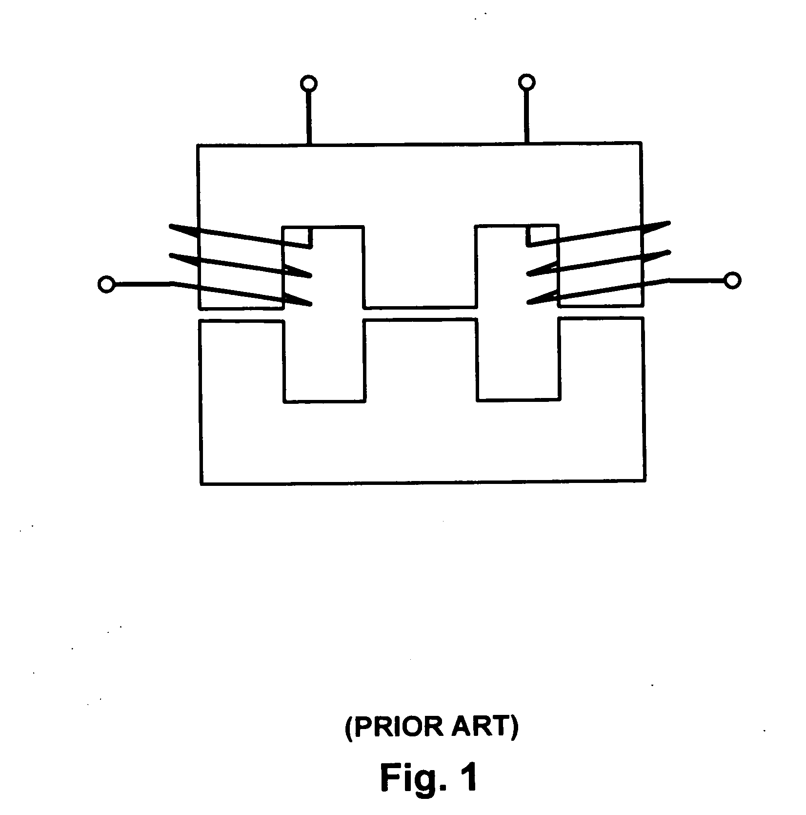
This requirement makes the multi-port electromagnetic device of FIG. 1 unsuitable because of its dependent inductive components.
However, the structure of the windings on the magnetic core for creating orthogonal magnetic flux is too complex.
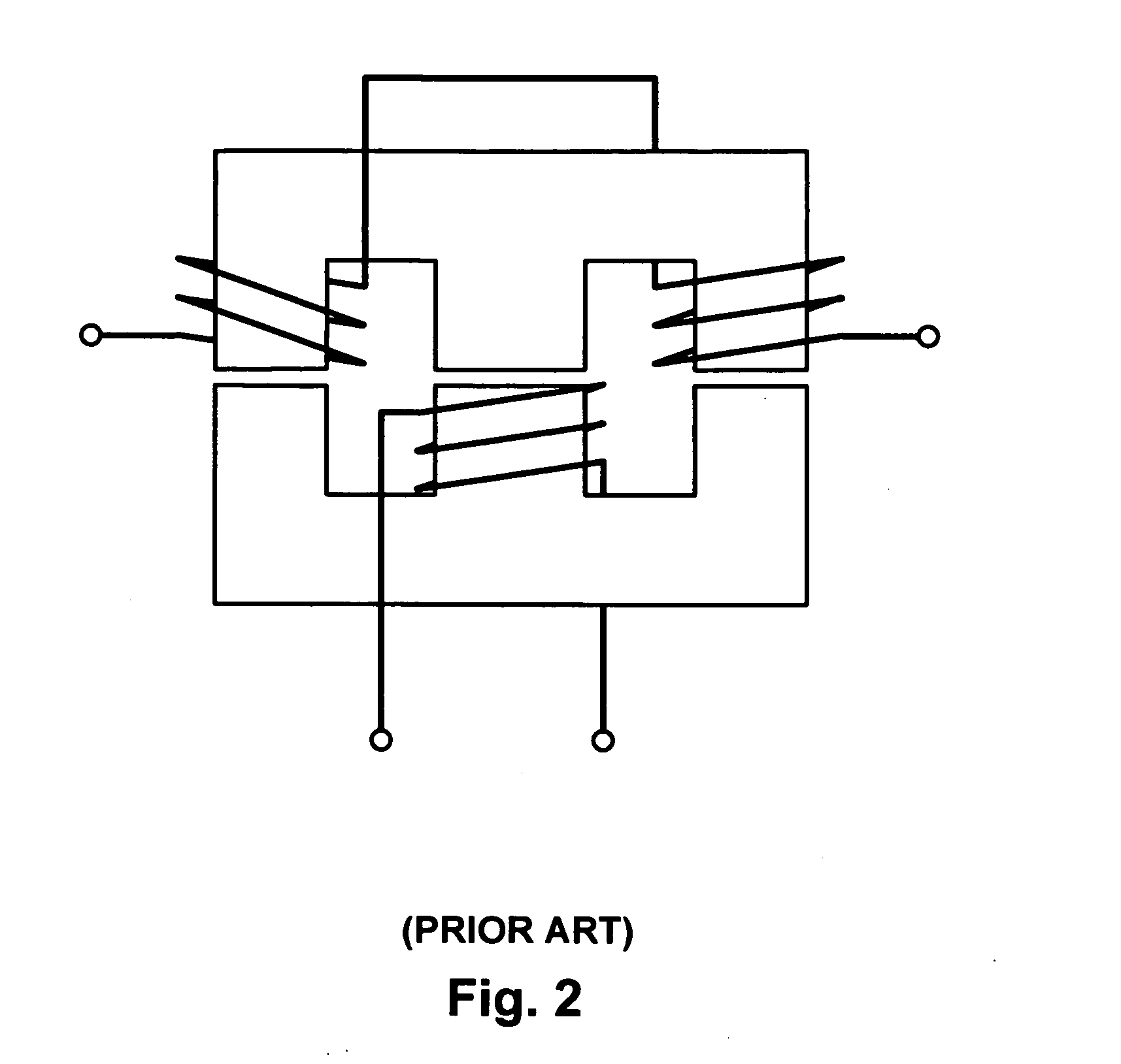
However, in the multi-port electromagnetic device of FIG. 2, the reluctances of the two outer legs of the E core must be identical, otherwise the magnetic flux generated by the winding on the middle leg is not equally distributed to the outer legs.
The low utilization of the inductive components may be a serious penalty in terms of size, weight and power density of the power supply.

Method used


Image

  • Power factor correction rectifier having independent inductive components
  • Power factor correction rectifier having independent inductive components
  • Power factor correction rectifier having independent inductive components

Examples


Embodiment Construction

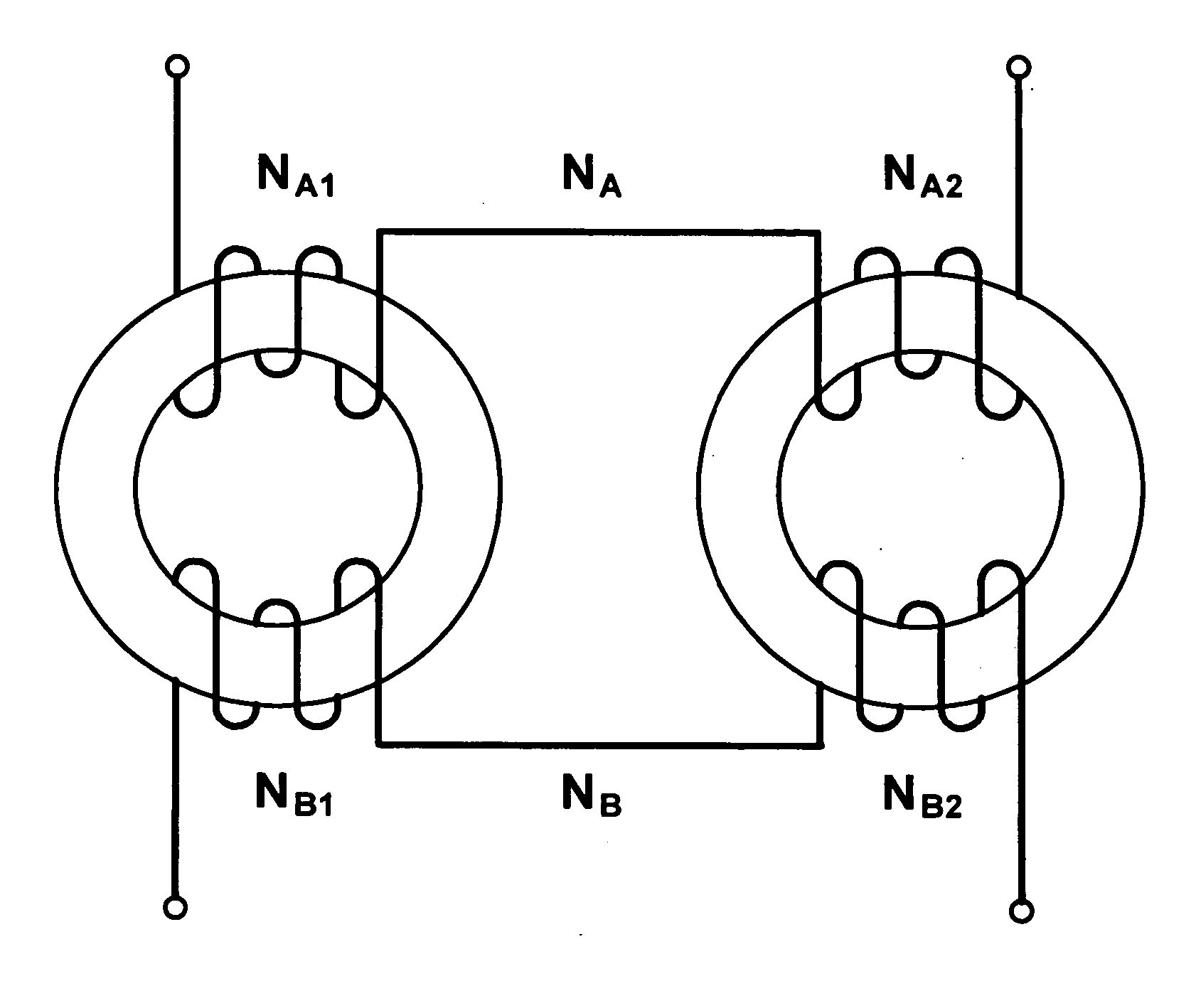
[0043] According to the present invention, a PFC rectifier employs magnetically independent windings of a multi-port device to increase the utilization of the magnetic core. More specifically, the PFC rectifier includes at least two converters each having a corresponding inductive component. In one embodiment, the two converters comprise boost converters, each being active during one half line cycle of an ac input voltage. The inductive components of the boost converters comprise magnetically independent windings of the multi-port electromagnetic device. The multi-port magnetic device has two magnetically independent first and second magnetic cores, which are coupled to each other via the two windings. The windings store decoupled magnetic energy in the first and second magnetic cores such that the two of windings are magnetically independent of each other. In one embodiment, one half of the winding turns is wound on the first core and the other half is wound on the second core. In ...


PUM


Abstract

A PFC circuit comprises a first converter and a second converter and a multi-port electromagnetic device. The first converter has a first inductive element and the second converter has a second inductive element. The multi-port electromagnetic device. comprises a first magnetic core having a first closed flux path and a second magnetic core having a second closed flux path, with the first closed flux path being independent of the second closed flux path. The first inductive element of the first boost circuit comprises a first winding that electromagnetically couples the first magnetic core to the second magnetic core and the second inductive element of the second boost circuit comprises a second winding that electromagnetically couples the first magnetic core to the second magnetic core independent of the electromagnetic coupling of the first winding such that current application in one windings does not induce a substantial voltage in the other.

Description

RELATED APPLICATIONS [0001] This application is continuation-in-part of Patent Application 11 / 062,446, filed oi Feb. 22, 2005, which is hereby incorporated by reference in its entirety.BACKGROUND OF THE INVENTION [0002] 1. Field of the Invention [0003] This invention relates to power factor correction (PFC) front-end rectifier, and more particularly to a PFC rectifier that has independently coupled inductive components. [0004] 2. Description of the Prior Art [0005] Electromagnetic devices have been used in a wide variety of power supply applications. These devices generally comprise a magnetic core and one or more windings. Some power supplies use multiple electromagnetic devices at various stages of their power conversion circuitry. Conventionally, magnetic cores of the multiple electromagnetic devices has been integrated to increase the power density and decrease the component count of power supplies. [0006] Known power conversion circuitry have used an integrated magnetic core to...

Claims


Application Information

Patent Timeline
IPC IPC(8): H01F27/24
CPCH01F3/10H01F27/34H01F30/06H01F38/16Y02P80/112H01F2027/408Y02P80/10
Inventor JANG, YUNGTAEKJOVANOVIC, MILAN
Owner DELTA ELECTRONICS INC
Learn More