Improved Plasma Torch for Ignition, Flameholding and Enhancement of Combustion in High Speed Flows

a plasma torch and high-speed flow technology, which is applied in the field of jet engine afterburners, scrapjets, ramjets and jet engine, can solve the problems of difficult optimization of combustion reaction, affecting mixing and atomization and the likelihood of fuel reliably, and difficult to ignite and flamehold. , to achieve the effect of improving fuel mixing, simple, robust and reliable, and enhancing combustion reaction

Inactive Publication Date: 2007-03-01
VIRGINIA TECH INTPROP INC
View PDF3 Cites 38 Cited by
  • Summary
  • Abstract
  • Description
  • Claims
  • Application Information

AI Technical Summary

Benefits of technology

[0010] It is therefore an object of the present invention to provide a simple, robust and reliable arrangement for ignition and flameholding in high velocity flow regimes which also improves fuel mixing and enhances the combustion reaction while being of reduced size and weight. It is another object of the invention to provide a structure in which ignition can be achieved with reduced delay.
[0011] In order to accomplish these and other objects of the invention, the basic invention provides a plasma torch with a fuel injector and heat exchanger which may be retrofitted to existing plasma torches or integrated in a new design; either of which provides improved fuel mixing and atomization and improved optimization of the combustion reaction as well as providing improved and controllable ignition and flame holding. Other aspects of the invention may be provided as perfecting features of the basic invention or inventive features which may be retrofitted to known plasma torch structures and which improve the performance thereof. More specifically, a combined plasma torch igniter / mixer / combustion reaction enhancer and a jet engine including the same are provided wherein the igniter / mixer / combustion reaction enhancer comprises a plasma torch including an anode an capable of producing a plasma plume, a heat exchanger for preheating fuel and cooling said anode, a nozzle for injecting preheated fuel into the plasma plume from a location adjacent the plasma plume, and an arrangement for passing feedstock material adjacent the anode.

Problems solved by technology

Ignition and flameholding is particularly difficult at flow velocity regimes approaching and above the speed of sound.
Upstream fuel injection is generally considered to be required in order to provide time for atomization and mixing of the fuel in a high speed gas flow prior to ignition but which is very limited due to restrictions on size of an engine usable in a practical aircraft.
Additionally, there appears to be a trade-off with the distance of the fuel injection point in advance of the igniter which affects mixing and atomization and the likelihood of the fuel reliably reaching the igniter.
Therefore optimization of the combustion reaction, especially for wide range operation, is difficult.
Moreover, all three of these requirements are currently addressed by separate mechanisms or arrangements, each of which has tended to be bulky and of significant weight, contrary to what is desirable in an aircraft engine.
Thus, attempts to improve the efficiency of any of them in regard to their function generally tends to increase bulk, weight or both while yielding only marginal improvements in engine performance.
However, simply using a plasma torch as an ignition source does not mitigate the problems of obtaining good fuel mixing or combustion enhancement.
Further, in such a system, as with ramps, cavities and pyrophoric compounds, use of known plasma torches is not significantly controllable to regulate the performance of the combustion system.
Further, difficulties and delays in achieving ignition due to insufficient atomization and mixing presents a substantial safety hazard.
Additionally, approaches to improvement of ignition, atomization, mixing and combustion enhancement known in the art have required structures which intrude into the high speed air flow; causing further disturbances and shock waves that may disrupt, for example, uniformity of fuel distribution (which often tends to follow the wavefronts of shock waves).

Method used


Image

  • Improved Plasma Torch for Ignition, Flameholding and Enhancement of Combustion in High Speed Flows
  • Improved Plasma Torch for Ignition, Flameholding and Enhancement of Combustion in High Speed Flows
  • Improved Plasma Torch for Ignition, Flameholding and Enhancement of Combustion in High Speed Flows

Examples


Embodiment Construction

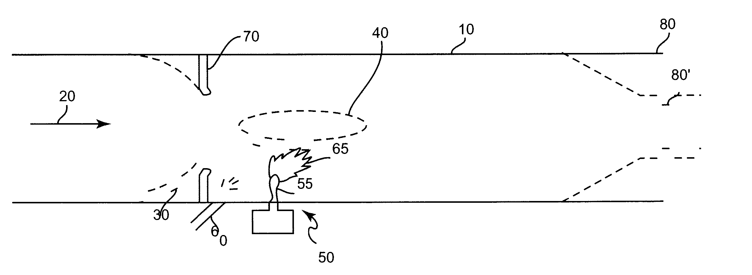
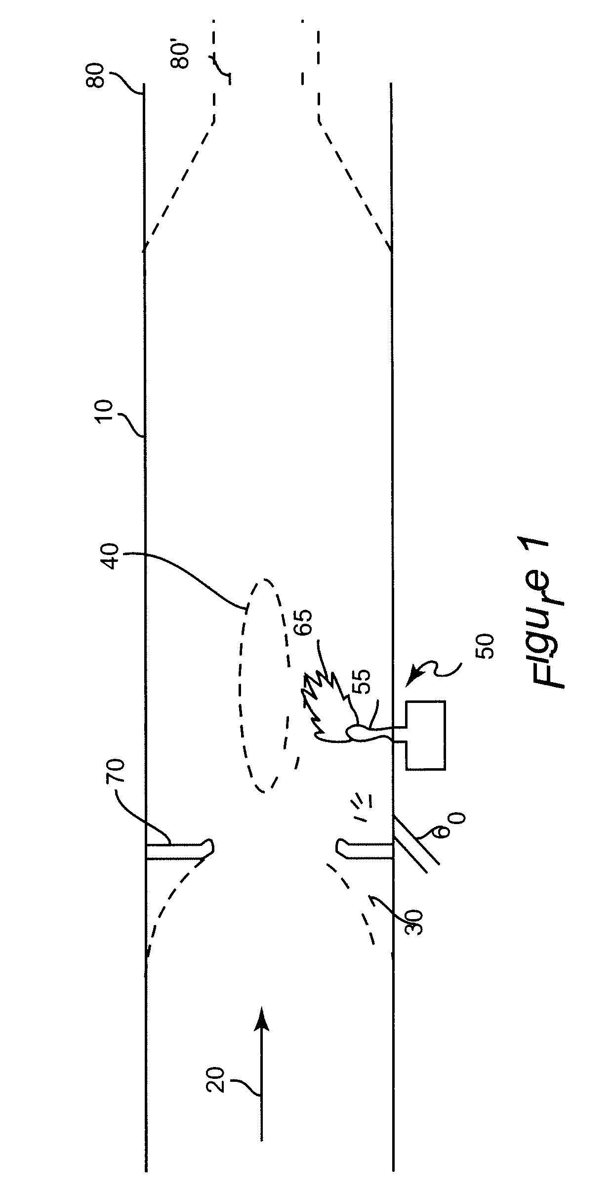
[0024] Referring now to the drawings, and more particularly to FIG. 1, there is shown a cross-sectional schematic view of a duct 10 having a high velocity gas flow 20 therein and the basic elements of a scramjet or ramjet engine or jet engine afterburner with which the invention may be employed. Duct 10 is illustrated for generality and would have a more complex internal shape for either of the above applications, as represented by schematically illustrated ramps / cavities 30. On the other hand, a straight-walled duct may, in fact, be preferred for some applications such as a large scale heat source for heat-driven process applications. The source of the high velocity gas flow is not important to the principles of the invention or its successful practice as long as the flow is such that the gas flow is compressed (e.g. by a compressor, a constriction and / or viscous drag at ramps / cavities 30 which also tend to direct expanding gases from ignition to the right, as illustrated) at a pos...


PUM


Abstract

Preheating of fuel and injection into a plasma torch plume fro adjacent the plasma torch plume provides for only ignition with reduced delay but improved fuel-air mixing and fuel atomization as well as combustion reaction enhancement. Heat exchange also reduced erosion of the anode of the plasma torch. Fuel mixing atomization, fuel mixture distribution enhancement and combustion reaction enhancement are improved by unsteady plasma torch energization, integral formation of the heat exchanger, fuel injection nozzle and plasma torch anode in a more compact, low-profile arrangement which is not intrusive on a highspeed air flow with which the invention is particularly effective and further enhanced by use of nitrogen as a feedstock material and inclusion of high pressure gases in the fuel to cause effervescence during injection.

Description

CROSS-REFERENCE TO RELATED APPLICATIONS [0001] This application claims priority of U.S. Provisional Patent Application 60 / 682,424, filed May 19, 2005, which is hereby fully incorporated by reference.STATEMENT OF GOVERNMENT INTEREST [0002] This invention was federally funded under NASA grant NAG-1-02108. The U.S. Government has certain rights in this invention.BACKGROUND OF THE INVENTION [0003] 1. Field of the Invention [0004] The present invention generally relates to jet engines and other applications including combustion in an environment of high speed gas flow and, more particularly, to so-called scramjets, ramjets and jet engine afterburners. [0005] 2. Description of the Prior Art [0006] Efficient and reliable operation of supersonic combustion ramjet (scramjet) engines and ramjet engines (which operate similarly but with sub-sonic flow regimes) and other applications needing combustion in high speed flow regimes (such as jet engine afterburners) relies on rapid and predictable ...

Claims


Application Information

Patent Timeline
Patent Type & Authority Applications(United States)
IPC IPC(8): F02C7/264
CPCF02K3/10F02K7/10F23R2900/00009F05D2220/10F05D2220/80
Inventor O'BRIEN, WALTER F.BILLINGSLEY, MATTHEW C.SANDERS, DARIUS D.SCHETZ, JOSEPH A.
Owner VIRGINIA TECH INTPROP INC
Why Eureka
Try Eureka