Technique for improving ion implanter productivity

a technology of ion implanter and productivity, applied in the field of ion implantation, can solve the problems of limited life of ion source running carbon or oxygen containing reactive species, reducing ion output, and problematic methods for generating carbon or oxygen ions, and achieve the effect of improving the productivity of an ion implanter

Active Publication Date: 2007-03-01
VARIAN SEMICON EQUIP ASSOC INC
View PDF86 Cites 23 Cited by
  • Summary
  • Abstract
  • Description
  • Claims
  • Application Information

AI Technical Summary

Benefits of technology

[0015] In another particular exemplary embodiment, the technique may be realized as a method for improving productivity of an ion implanter having an ion source chamber. The method may comprise supplying a gaseous substance to the ion source chamber, the gaseous substance comprising one or more reactive species for generating ions for the ion implanter. The method may also comprise stopping the supply of the gaseous substance to the ion source chamber. The method may further comprise supplying a chlorine containing gas to the ion source chamber for a period of time after stopping the supply of the gaseous substance.
[0017] In yet another particular exemplary embodiment, the technique may be realized as a method for improving productivity of an ion implanter having an ion source chamber. The method may comprise supplying the ion source chamber with a gaseous mixture of a hydrogen containing gas and one or more reactive species. The method may also comprise generating a plasma in the ion source chamber based on the gaseous mixture, wherein the plasma contains ions generated from the one or more reactive species for use in the ion implanter, and wherein the plasma further removes one or more compounds from the ion source chamber.
[0021] In another particular exemplary embodiment, the technique may be realized as a method for improving productivity of an ion implanter having an ion source chamber. The method may comprise supplying a gaseous substance to the ion source chamber, the gaseous substance comprising one or more reactive species for generating carbon ions for the ion implanter. The method may also comprise stopping the supply of the gaseous substance to the ion source chamber. The method may further comprise supplying a hydrogen containing gas to the ion source chamber for a period of time after stopping the supply of the gaseous substance, the hydrogen containing gas also comprising at least one sputtering agent. The method may additionally comprise generating a plasma based on the hydrogen containing gas, wherein the plasma removes one or more metal compounds from the ion source chamber.

Problems solved by technology

Existing methods for generating carbon or oxygen ions are problematic.
One significant problem is a limited lifetime of ion sources running carbon or oxygen containing reactive species.
Reaction by-products can accumulate inside an ion source chamber within a few hours, reducing ion output or causing the ion output to become unstable.
Replacement or maintenance of an ion source chamber results in an extended downtime for an ion implanter.
In addition, carbon or oxygen ion generation in an ion source chamber tend to cause a negative impact on subsequent ion generation processes carried out in that ion source chamber.
The “poisoning” effect can adversely change surface chemistry for subsequent reactions in the ion source chamber.

Method used


Image

  • Technique for improving ion implanter productivity
  • Technique for improving ion implanter productivity
  • Technique for improving ion implanter productivity

Examples


Embodiment Construction

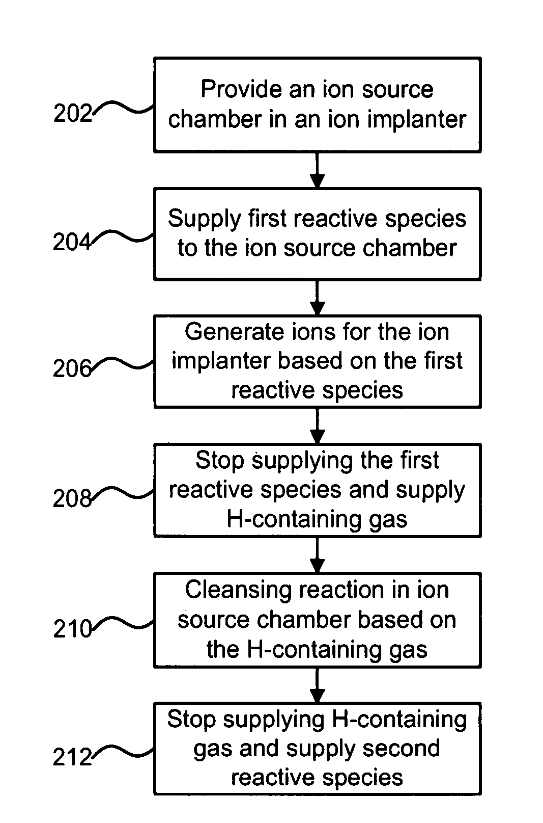
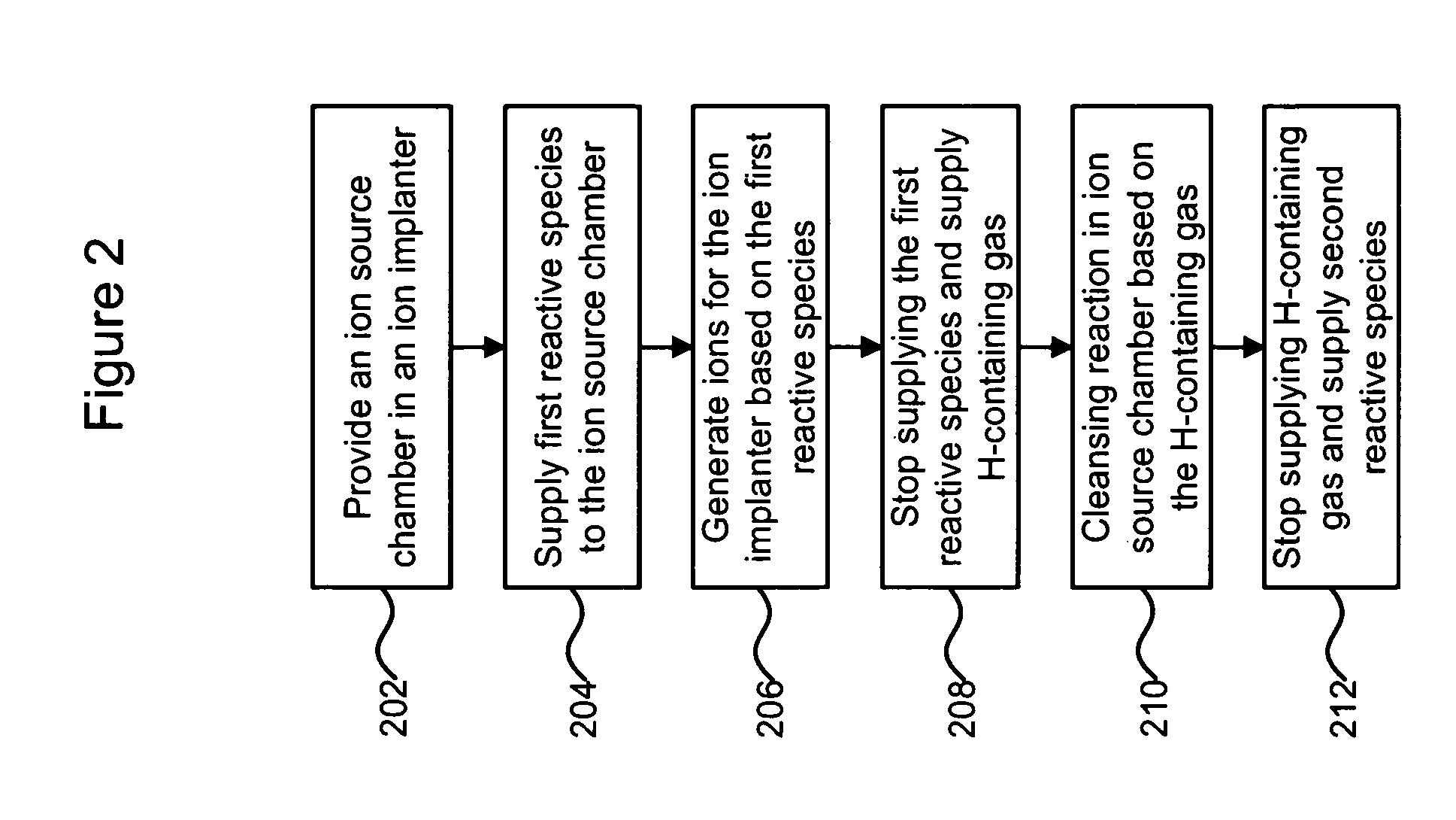
[0027] Embodiments of the present disclosure may improve productivity of an ion implanter by reducing or eliminating ion source chamber poisoning. An ion source chamber may be cleaned or reconditioned with a hydrogen containing gas or a chlorine containing gas between ion generation processes. A variety of endpoint detection methods may be employed to know when to stop the cleaning process. Alternatively, a hydrogen containing gas may be mixed with or act as a diluent for one or more ion-generating reactive species, such that the ion source chamber is cleaned or reconditioned concurrently with an ion generation process. As a result, the ion source may become more productive in generating ions since a cleaning of the ion source chamber is less frequently required. When cleaning of the ion source chamber is required, it may be carried out more effectively and more efficiently.

[0028] Referring to FIG. 2, there is shown a flow chart illustrating an exemplary method for improving ion im...


PUM


Abstract

A technique for improving ion implanter productivity is disclosed. In one particular exemplary embodiment, the technique may be realized as a method for improving productivity of an ion implanter having an ion source chamber. The method may comprise supplying a gaseous substance to the ion source chamber, the gaseous substance comprising one or more reactive species for generating ions for the ion implanter. The method may also comprise stopping the supply of the gaseous substance to the ion source chamber. The method may further comprise supplying a hydrogen containing gas to the ion source chamber for a period of time after stopping the supply of the gaseous substance.

Description

CROSS-REFERENCE TO RELATED APPLICATIONS [0001] This patent application claims priority to U.S. Provisional Patent Application No. 60 / 712,395, filed Aug. 31, 2005, which is hereby incorporated by reference herein in its entirety.FIELD OF THE DISCLOSURE [0002] The present disclosure relates generally to ion implantation and, more particularly, to a technique for improving ion implanter productivity. BACKGROUND OF THE DISCLOSURE [0003] Ion implantation is a process for depositing chemical species into a substrate by direct bombardment of the substrate with high-energy ions. In semiconductor fabrication, ion implanters are used primarily for doping processes that alter the type and level of conductivity of target materials. A precise doping profile in an integrated circuit (IC) substrate and its thin-film structure is often crucial for proper IC performance. To achieve a desired doping profile, one or more ion species may be implanted in different doses and at different energies. [0004]...

Claims


Application Information

Patent Timeline
IPC IPC(8): H01J37/317
CPCH01J37/08H01J37/3171H01J2237/022H01J2237/31705H01J2237/0822H01J2237/0827H01J2237/082
Inventor CHANEY, CRAIG R.LOW, RUSSELL J.ENGLAND, JONATHAN GERALD
Owner VARIAN SEMICON EQUIP ASSOC INC
Why Eureka
Try Eureka