Retardation film, manufacturing method thereof, polarizing plate and liquid crystal display apparatus

a technology of polarizing plate and film, which is applied in the direction of polarizing elements, instruments, optics, etc., can solve the problems of reducing the thickness of the polarizing plate used in the polarizing plate, the growth of the liquid crystal display apparatus and the polarizing plate, and the yield reduction, so as to achieve the effect of improving the curl

Active Publication Date: 2007-03-01
KONICA MINOLTA OPTO
View PDF6 Cites 108 Cited by
  • Summary
  • Abstract
  • Description
  • Claims
  • Application Information

AI Technical Summary

Benefits of technology

[0056] The present invention provides a retardation film suitable for the manufacture of a thin-film polarizing plate characterized by improved curls, a method of manufacturing such a retardation film, and a polarizing plate and liquid crystal display apparatus using this film.

Problems solved by technology

In recent years, there is a tendency for the growing size of a liquid crystal display apparatus and the reducing thickness of the polarizing plate used therein.
One of the big problems in the process of manufacturing is concerned with the absolute value for the size of curl when the polarizing plate is bonded on the glass of a liquid crystal cell, i.e. the height of the end of the cut polarizing plate raised from the horizontal plane or the height of the raised central portion of the cut polarizing plate.
This will take much time and labor.
Alternatively, this problem may lead to the failure to use the panel per se, and hence a still bigger problem of reduced yield.
This problem is serious especially when a thin film polarizing plate is manufactured.
However, when this method is used, there is a reduction of the yield due to bonding error.
Further, it is often very difficult to control the curl of the final polarizing plate product due to the lack of direct bondage with the polarizing film.
However, these techniques are not sufficient to control the curl of the polarizing plate used in the manufacture of a large-sized liquid crystal display apparatus.

Method used


Image

  • Retardation film, manufacturing method thereof, polarizing plate and liquid crystal display apparatus
  • Retardation film, manufacturing method thereof, polarizing plate and liquid crystal display apparatus
  • Retardation film, manufacturing method thereof, polarizing plate and liquid crystal display apparatus

Examples


example

[0373] The following describes the present invention with reference to Examples, without the present invention being restricted thereto:

[0374]>

(Preparation of Retardation Film 101)

[0375] The present inventors used the cellulose esters where the replacement ratio and type of the substituent given in Table 1 were variously changed.

TABLE 1TotalCellulosePropionylreplacementestersAcetyl groupgroupratioA1.60.82.4B1.60.92.5C1.70.92.6D1.81.02.8E2.7—2.7

[0376]

Particles (Aerosil R972V (manufactured by Japan11 parts by massAerosil))(average diameter of the primary particles: 16 nm;apparent specific weight: 90 g / liter)Ethanol89 parts by mass

[0377] The inventors stirred the above mixture by a dissolver for 50 minutes and dispersed the particles a Manthon Gaulin.

[0378]

[0379] The inventors prepared a particle-added solution by taking the steps of adding a cellulose ester A into methylene chloride in a dissolution tank; heating the mixture until the cellulose ester was completely dissolved; fi...

example 2

[0437] (Preparation of the Polarizing Plate Protective Films Provided with Antireflection Layer)

[0438] Using the above prepared polarizing plate protective films 201 through 203, the present inventors prepared the polarizing plate protective film provided with antireflection layer according to the following procedure.

[0439] The present inventors measured the refractive index of each layer constituting the antireflection layer according to the following method.

[0440] (Refractive Index)

[0441] The refractive index of each refractive index of the sample coated on the above prepared hard coated film separately for each layer was calculated from the result of measuring the spectral reflection factor by a spectrophotometer. After roughening the rear surface on the sample measuring side, the process of light absorption was applied by a black spray to prevent the light from being reflected on the rear surface. Then the spectrophotometer U-4000 (manufactured by Hitachi, Ltd.) was used to ...

example 3

[0464] The present inventors prepared the following retardation films 401 through 403 in the same procedure as that of Example 1 except that the following process of heat treatment was added, when the retardation film 101 of the Example 1.

[0465]

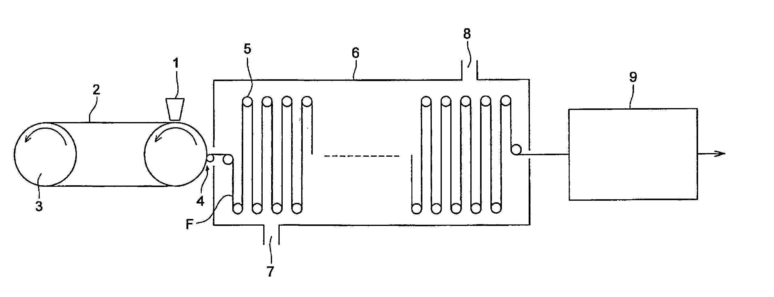
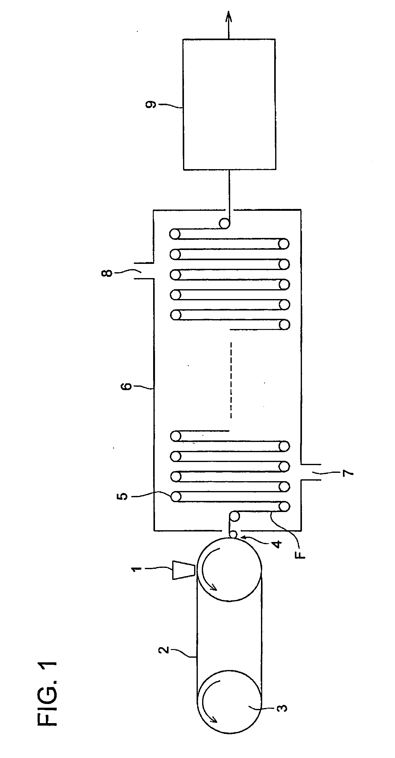
[0466] The present inventors produced a film by taking the steps of drawing the web by the tenter, and drying the web by dry air at 105° C. until the amount of residual solvent was reduced to 0.3% by mass in the process of conveyance and drying by the roll with a plurality of webs arranged on the upper and lower portions thereof. After that, the film having been produced was pressurized at a pressure of 10 kPa along the thickness of the film by the nip rolls provided in multiple stages, when the film was heat-treated for 20 minutes in an atmosphere of 110° C. with the atmosphere change rate amounting to 25 times per hour. After that, the film was cooled down to the room temperature and was taken up. Thus, the present inventors produces a ret...


PUM

PropertyMeasurementUnit
thickness direction retardation Rtaaaaaaaaaa

Abstract

A film bonded to a polarizer of a polarizing plate, has a surface A and a surface B opposite to the surface A; and a thickness of 10 μm to 70 μm; wherein a refractive index difference between the surface A and the surface B is 5×10⁻⁴ to 5×10⁻³.

Description

[0001] This application is based on Japanese Patent Application No. 2005-245741 filed on Aug. 26, 2005, in Japanese Patent Office, the entire content of which is hereby incorporated by reference. BACKGROUND OF THE INVENTION [0002] The present invention relates to a retardation film, manufacturing method thereof, polarizing plate and liquid crystal display apparatus, particularly to a retardation film with its curl having been improved for suitable use in a polarizing plate, the manufacturing method thereof, the polarizing plate and liquid crystal display apparatus using this retardation film. [0003] The liquid crystal display apparatus is characterized by low voltage and low power consumption. It can be directly coupled to an IC circuit, and can be built into a thin configuration. Because of these advantages, the liquid crystal display apparatus has an extensive use as a display for word processors or personal computers. This liquid crystal display apparatus is basically structured ...

Claims


Application Information

Patent Timeline
Patent Type & Authority Applications(United States)
IPC IPC(8): G02F1/1335
CPCG02B5/3083G02F1/13363G02F1/133528G02B5/30
Inventor UMEDA, HIROKIKUZUHARA, NORIYASUINAGAKI, SHINJI
Owner KONICA MINOLTA OPTO
Why Eureka
Try Eureka