Ceramic filter

a ceramic filter and filter body technology, applied in the field of ceramic filters, can solve the problems of limiting the maximum temperature of the ceramic filter, difficult control and lack of versatility, and complex structure, and achieve the effects of reducing temperature rise, simple structure, and small amount of heat generated by soot burning

Active Publication Date: 2007-03-08
NGK INSULATORS LTD
View PDF10 Cites 6 Cited by
  • Summary
  • Abstract
  • Description
  • Claims
  • Application Information

AI Technical Summary

Benefits of technology

[0011] According to this invention, the amount of exhaust gas flowing into the inlet of each honeycomb segment is smaller in the central portion than in the peripheral portion. Accordingly, the amount of soot accumulated in the vents of each honeycomb segment is relatively smaller in the central portion than in the peripheral portion, and therefore the amount of heat generated by soot burning is small in the central portion. This reduces temperature rise during recycling and further limits the maximum temperature of the ceramic filter.
[0012] Accordingly, this ceramic filter reduces the possibility that a crack or catalyst deterioration occurs in recycling. The ceramic filter makes it possible to limit the maximum temperature with a simple structure, and therefore requires neither a peripheral instrument such as a sensor nor complicated control.

Problems solved by technology

This structure is complex and has the problems of the difficulty of control and the lack of versatility.
This reduces temperature rise during recycling and further limits the maximum temperature of the ceramic filter.

Method used


Image

  • Ceramic filter
  • Ceramic filter
  • Ceramic filter

Examples


example

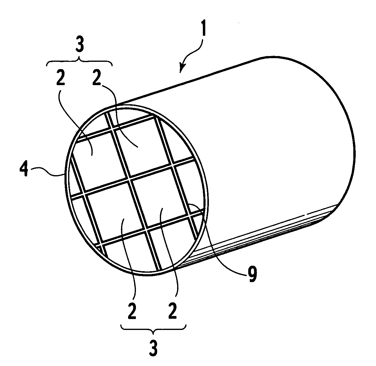
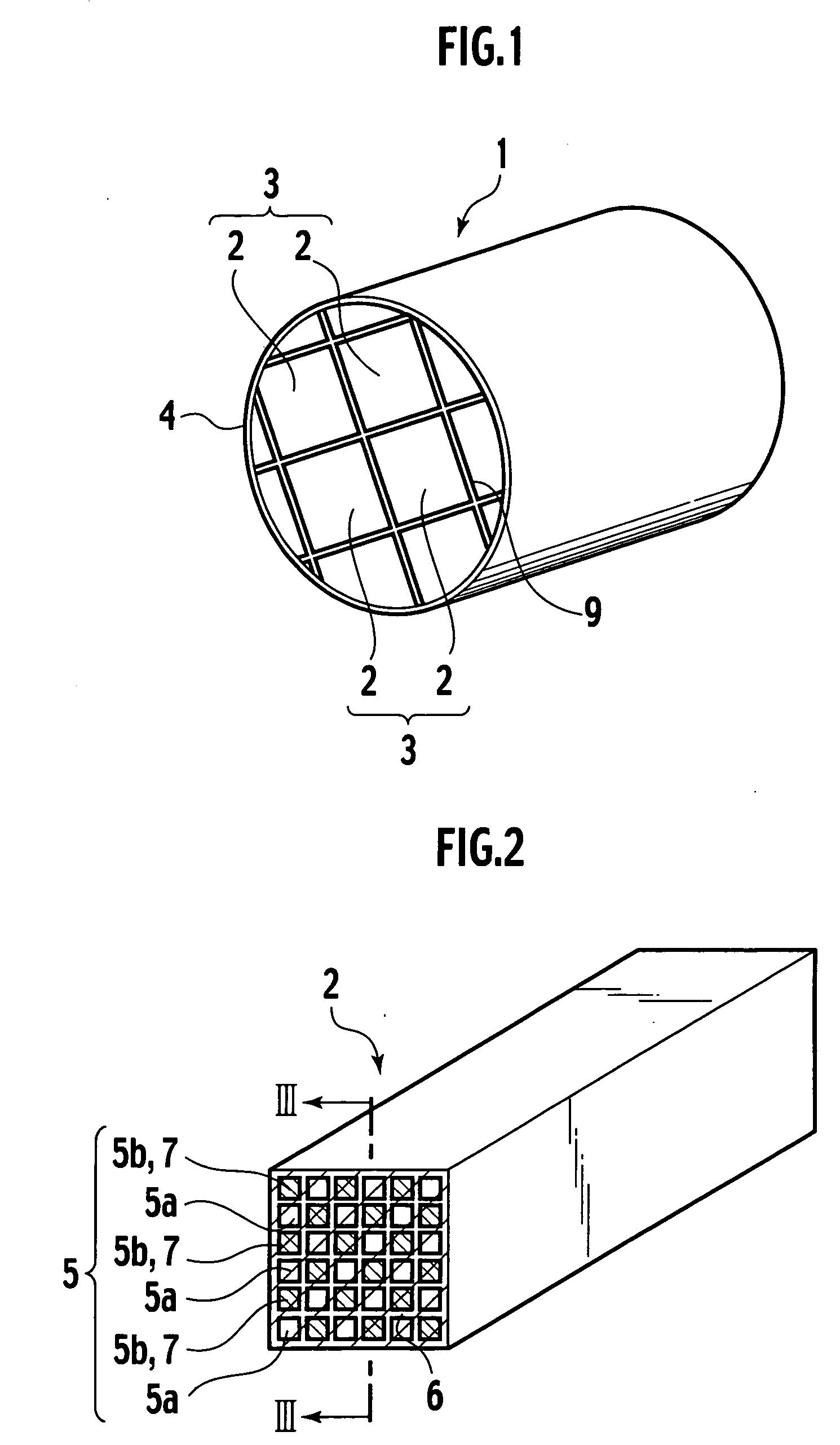
[0052] Honeycomb segments were prepared, each of which has a square cross section with a side length of 35 mm. The plurality of honeycomb segments are bonded together, thus preparing cylindrical ceramic filters (DPF) illustrated in FIG. 1. The length and number of honeycomb segments integrated therein and the outer diameter of the ceramic filter (DPF) are shown in Table 1.

[0053] The wording “cell structure” in Table 1 means the inlet size of vents formed in the honeycomb segment used. The ratio “10 / 300” indicates (wall thickness) / (cell density). The wall thickness of “10” indicates 10 mill (1 mill=0.0254 mm). The cell density of “300” indicates 300 cpsi (cell per square inch).

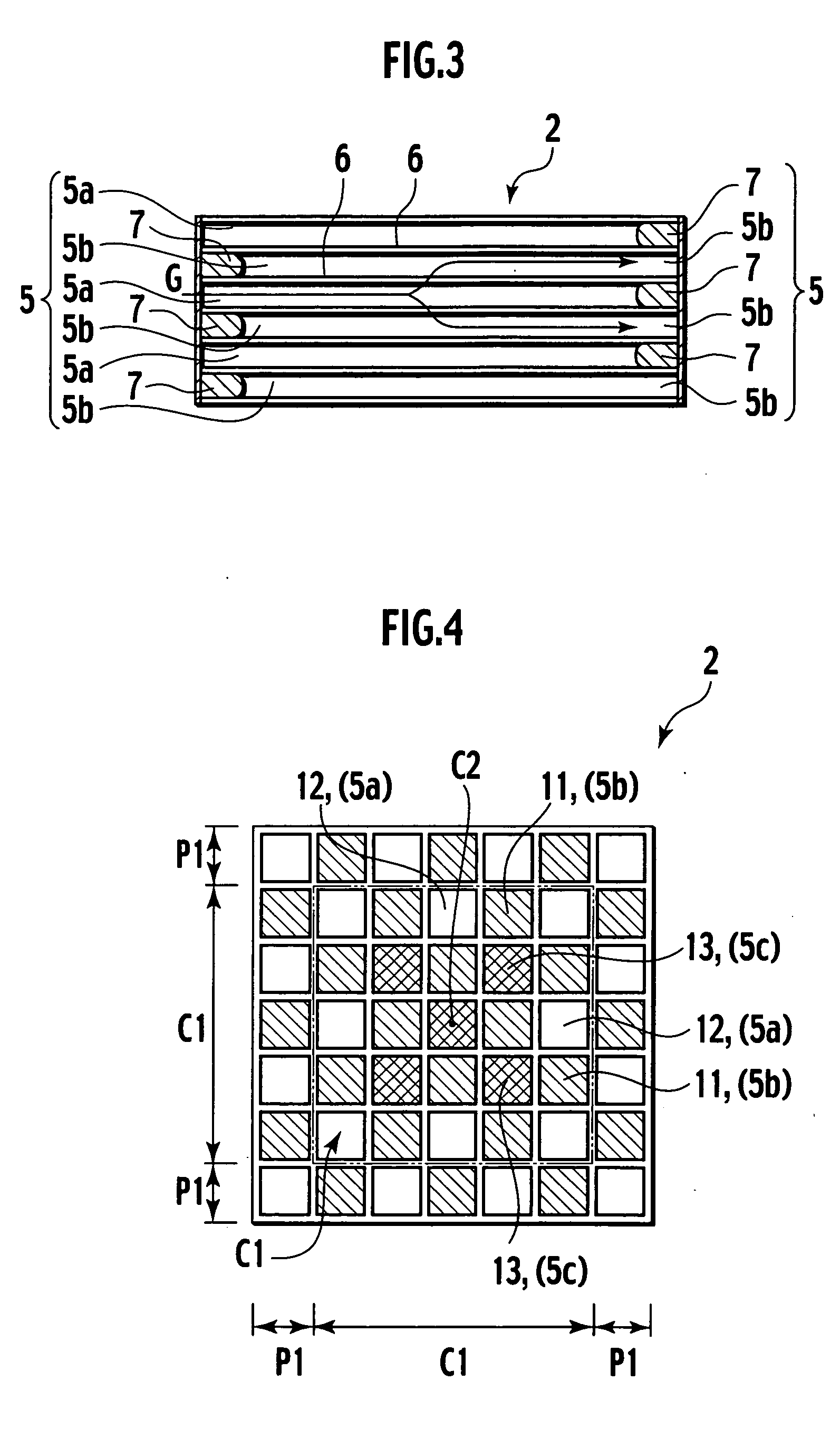
[0054] The wording “additional filling number in the central portion” means the number of inlets of vents additionally filled in the central portion of a checkerboard pattern in which filled inlets and non-filled open inlets are alternately placed to be neighboring to each other. The wording “additional filli...


PUM

PropertyMeasurementUnit
side lengthaaaaaaaaaa
temperatureaaaaaaaaaa
pressureaaaaaaaaaa

Abstract

A filling percentage of a central portion is larger than that of a peripheral portion at the inlet end surface of an exhaust gas of a honeycomb segment (2) constituting a ceramic filter due to additional filling (13). Thus, an amount of soot accumulated in vents (5) in the central portion of each honeycomb segment (2) is less relative to that in the peripheral portion. This decreases a quantity of heat generated by burning of soot in the central portion, and reduces temperature rise during recycling, thus limiting the maximum temperature of the ceramic filter (1).

Description

TECHNICAL FIELD [0001] The present invention relates to a ceramic filter used as a diesel particulate filter (DPF) or other collection filter. This filter captures and removes particulates such as soot which are contained in exhaust gas from a diesel engine or the like. BACKGROUND ART [0002] A DPF is disclosed in Japanese Unexamined Patent Application Publication Laid-open No. Sho 56-129020. Porous honeycomb segments made of ceramic such as silicon carbide are bonded together with bonding layers made of cement to be formed into a honeycomb assembly. This honeycomb assembly is shaped into a predetermined shape such as a circular cross section. Then, the periphery thereof is coated with a coating material layer. This DPF is placed in an exhaust system of a diesel engine to be used for cleaning exhaust gas. [0003] Each of the honeycomb segments is partitioned by porous walls and has a large number of vents extending therethrough in the axial direction. Neighboring vents have one end po...

Claims


Application Information

Patent Timeline
Patent Type & Authority Applications(United States)
IPC IPC(8): B01D39/20B01D46/24F01N3/022
CPCB01D46/2451B01D46/2459B01D46/2466B01D2046/2492Y02T10/20B01D2279/30F01N3/0222F01N2330/30F01N2330/48B01D2046/2496Y02T10/12B01D46/2498B01D46/2484B01D46/2478B01D39/20
Inventor MIZUTANI, TAKASHI
Owner NGK INSULATORS LTD
Why Eureka
Try Eureka