Radio frequency identification transponder antenna

a radio frequency identification and transponder chip technology, applied in the field of radio frequency identification transponders, can solve the problems of complex process and fabrication, high cost, and substantial complexity of the relatively large structure, and achieve the effect of low input impedance, low resistance, and simplified matching of the antenna base impedance to the input impedance of the assembled transponder chip

Active Publication Date: 2007-03-08
SMARTRAC TECHNOLOGY GMBH
View PDF8 Cites 243 Cited by
  • Summary
  • Abstract
  • Description
  • Claims
  • Application Information

AI Technical Summary

Benefits of technology

[0021] It is a particular advantage of the invention that matching the base impedance of the antenna to the input impedance of the assembled transponder chip can be simplified especially in transponder chips of low input impedance resulting from low resistance (real component <50Ω and / or high input capacitance including parasitic impedances resulting from the type of assembly).
[0022] A further advantage of the invention resides in the improved near field characteristic which has a pronounced direction characteristic. The RFID transponder also permits various mounting shapes and improved testing and programming, for instance by RFID transponders in a web structure during fabrication as well as for processing rolled goods in printers and dispensing apparatus.
[0023] Flexible assembly is made possible by the electrical separation of the spatially large resonant structure from the relatively small impedance-matching structure. This is one of the essential advantages of the invention since the high degree of geometric precision need be applied only to the smaller surface area, i.e. the microchip and the impedance-matching structure. This results in significant cost reductions, since the complexities relating to the geometric precision in an assembly operation increase disproportionally with respect to the surface of the structures.
[0024] The separation of the impedance-matching structure and resonant structure yields the further advantage that in case the microchips is changed only the impedance-matching structure need be matched while the resonant structure and its far field characteristic remain unchanged.
[0025] The separation of the impedance-matching structure from the resonant structure also makes possible the utilization of several resonant structures of different spatial lay-out for one transponder.
[0026] The formation on a common support, regardless of whether one or both surfaces of the support are utilized or whether the structures are each formed on a separate support is among the further advantageous features of the invention.

Problems solved by technology

The drawback of such prior art devices is that the desired optimum matching of the microchip to known structures is not only complex in terms of process and fabrication, but also, and because of it, expensive.
The fabrication of the transponder necessitates high geometric precision which leads to substantial complexities in the relatively large structures.
Another disadvantage of prior art devices is the likelihood of the microchips being damaged or destroyed when exposed to electrostatic discharges.
The useful life and proper functioning of the transponders are, therefore, negatively affected and at best uncertain.

Method used


Image

  • Radio frequency identification transponder antenna
  • Radio frequency identification transponder antenna
  • Radio frequency identification transponder antenna

Examples


Embodiment Construction

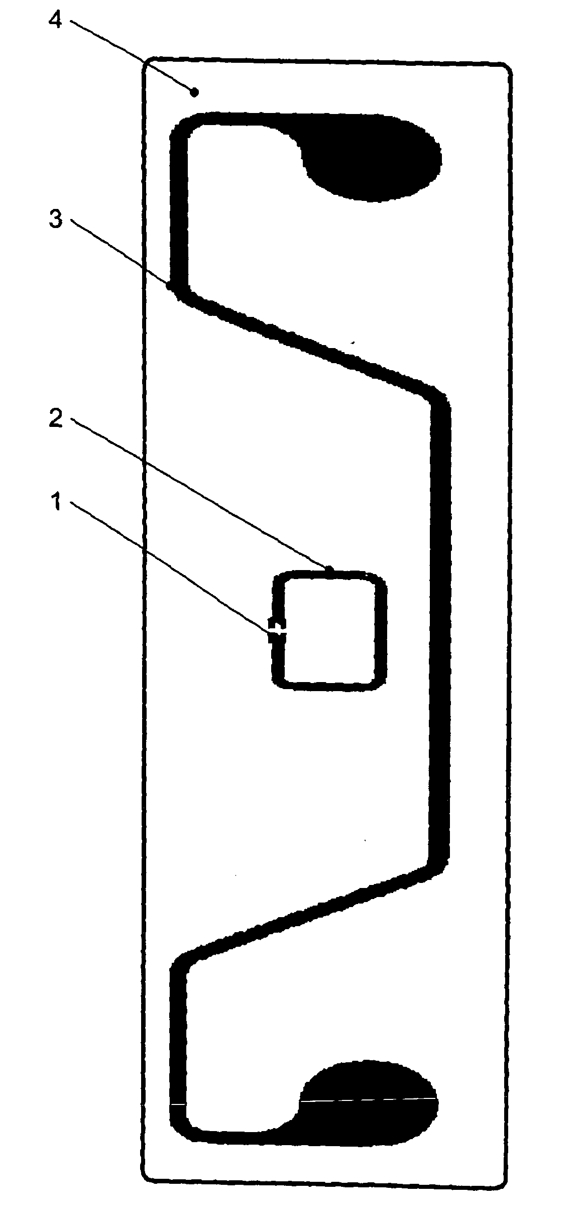
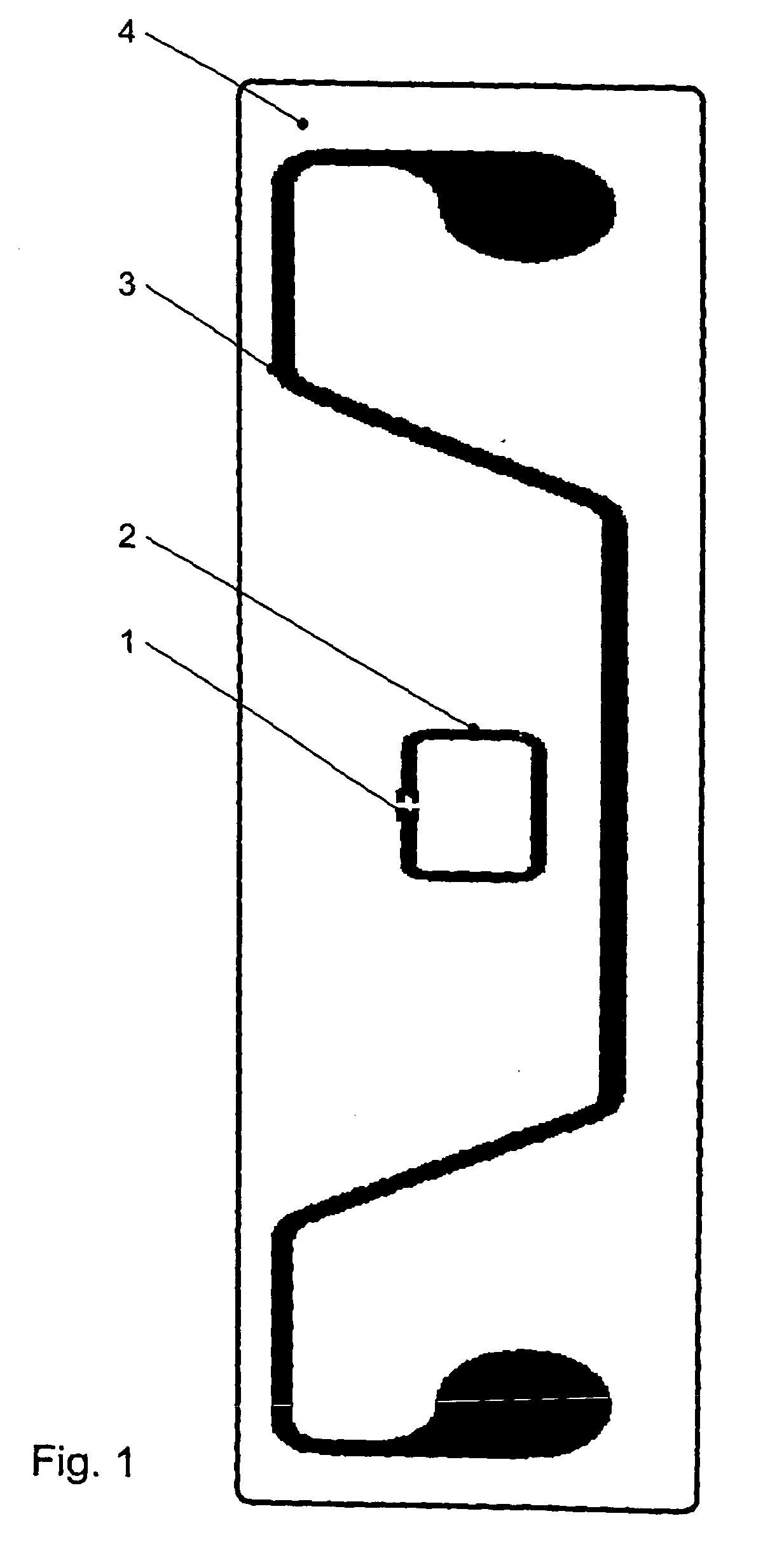
[0043]FIG. 1 schematically depicts a RFID transponder provided with a microchip 1, an impedance-matching structure 2 and a resonant structure 3. The components are mounted on a substrate 4 which may be a flexible material such as, for example, a copper plated polyethylene terephthalate film. The impedance-matching structure has been fabricated by an etching process and is structured as a rectangular loop.

[0044] The resonant structure 3 is of an M-shaped structure and in accordance with the invention, it is not galvanically connected to the loop structure 2 including the microchip 1.

[0045] For the sake of clarity and convenience like elements will hereafter be identified by like reference numerals.

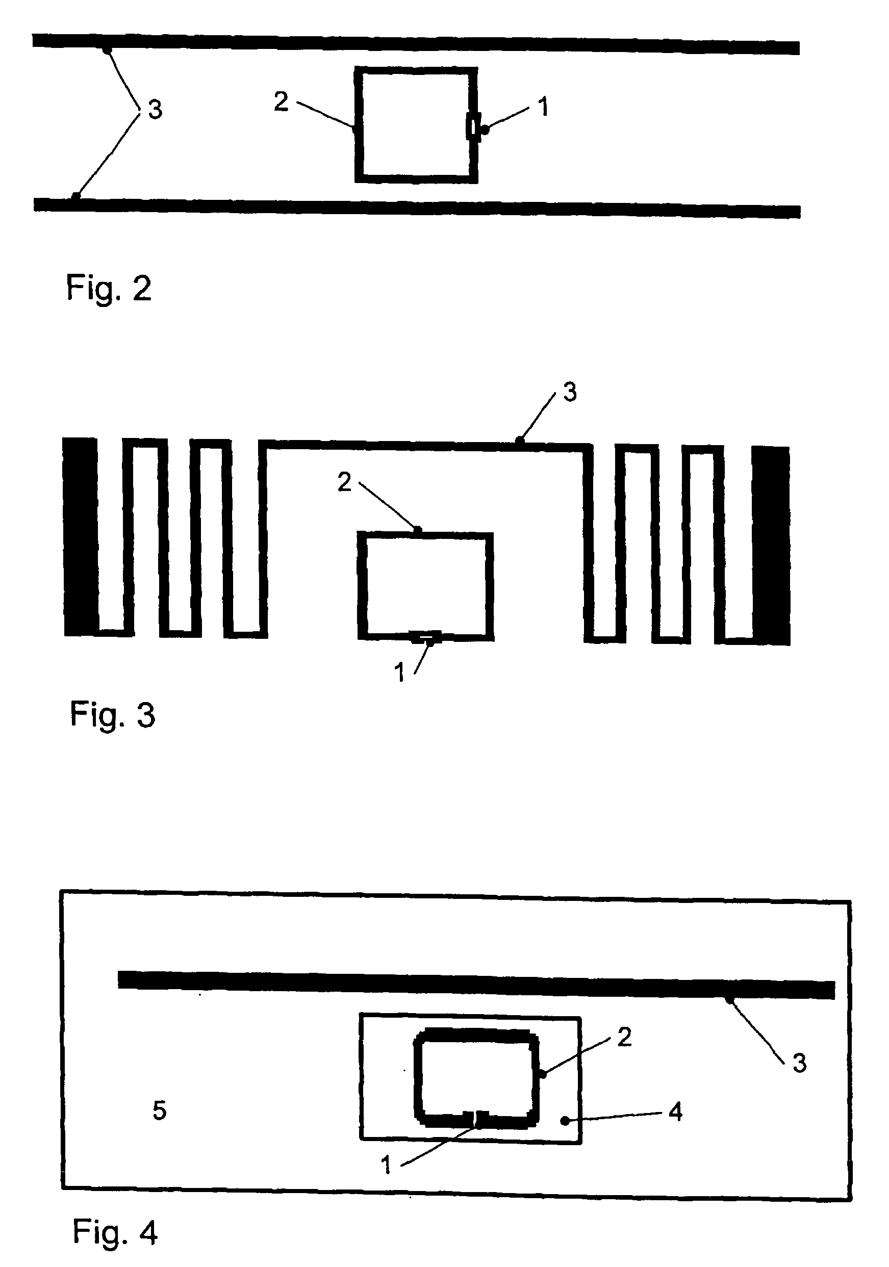
[0046]FIG. 2 schematically shows a RFID transponder in accordance with the invention with the impedance-matching structure 2 being configured as a substantially square loop. The resonant structure 3 is formed by two parallel spaced strip structures accommodating between them loop structu...


PUM


Abstract

A RFID transponder having a microchip or integrated circuit, an impedance-matching structure and a resonant structure mounted on at least one substrate and connected to each other by an electric field.

Description

BACKGROUND OF THE INVENTION [0001] 1. Field of the Invention [0002] The invention, in general, relates to a radio frequency identification transponder and, more particularly, to a radio frequency identification transponder antenna. [0003] Radio frequency identification, hereafter sometimes referred to as “RFID” makes it possible without physical or visual contact to read and store physical data and in the context of the instant invention will be understood generically to refer to a complete technical infrastructure. As a rule, a RFID system includes a transponder, also known as a tag or smart label, a transmission and receiving unit und their integration into servers, services and other systems. It is the transponder to which the instant invention relates. [0004] 2. The Prior Art [0005] RFID transponders including a microchip, a resonant structure and an impedance matching structure are well known in the art. Usually, the transponder is connected galvanically with the resonant and i...

Claims


Application Information

Patent Timeline
Patent Type & Authority Applications(United States)
IPC IPC(8): H01Q1/50
CPCG06K19/07749H01Q1/38H01Q1/2208G06K19/07756
Inventor GALLSCHUETZ, SEBASTIANRUPRECHT, HARALD
Owner SMARTRAC TECHNOLOGY GMBH
Why Eureka
Try Eureka