Method and apparatus for optimizing aerosol generation with ultrasonic transducers

a technology of ultrasonic transducers and aerosols, applied in water installations, disinfection, construction, etc., can solve the problems of aerosol formation from liquid their performance, noticeable deterioration of transducers, etc., and achieve the effect of reducing the effectiveness of transducers

Active Publication Date: 2007-03-08
ALTAPURE
View PDF12 Cites 24 Cited by
  • Summary
  • Abstract
  • Description
  • Claims
  • Application Information

AI Technical Summary

Benefits of technology

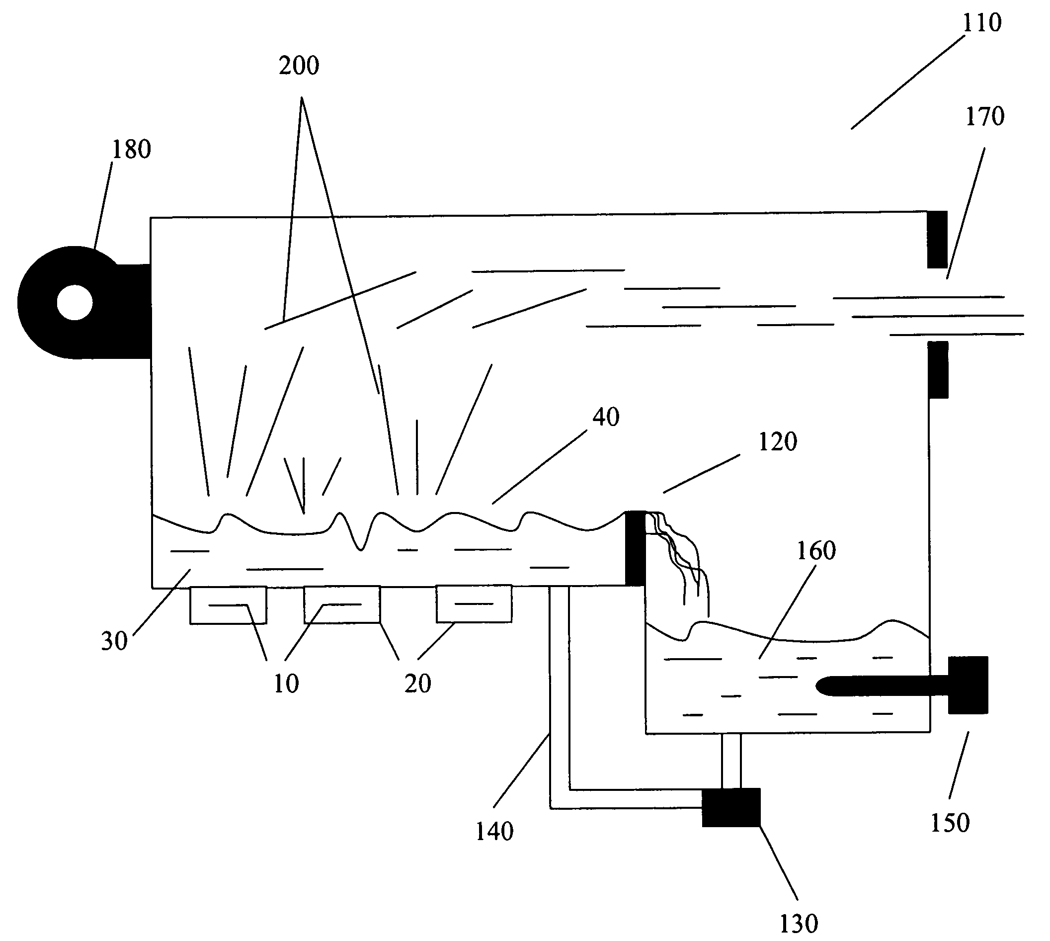
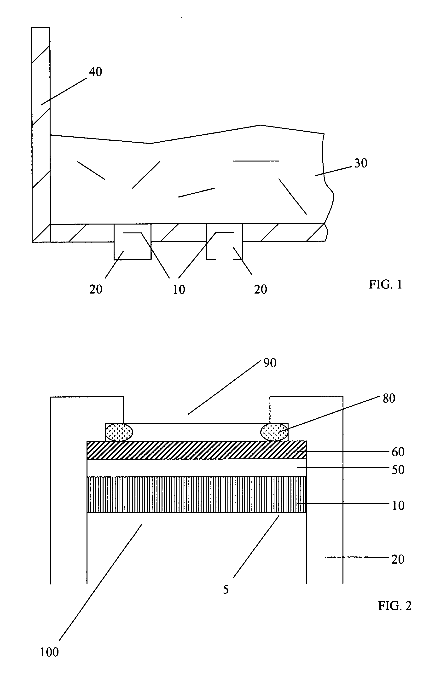
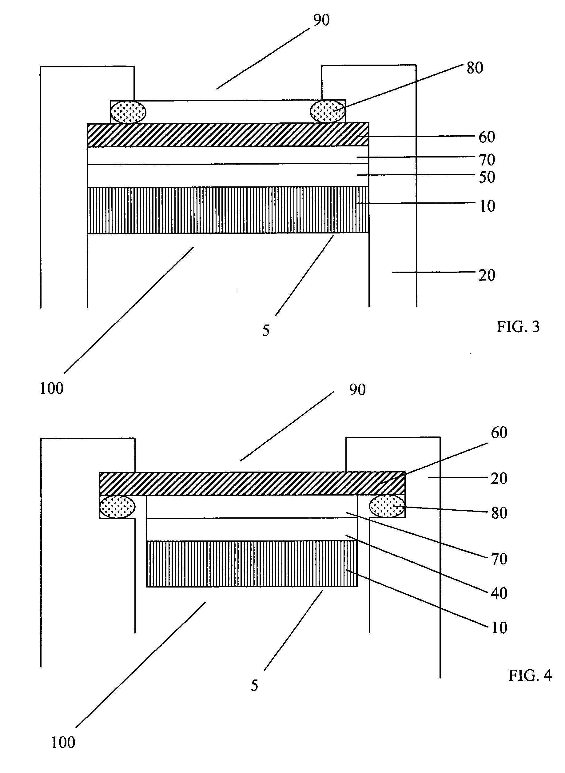
[0024] The present invention provides a protected transducer and method of protecting and enhancing a transducer that is capable of operating at a high energy output transmitted to a liquid without burning and / or damaging the transducer(s) or the adhesive / bonding agent with which it interfaces, or otherwise diminishing the effectiveness of the transducer, while avoiding issues such as, but not limited to, needing to add cooling mechanisms for the transducer(s), reflected energy resulting from mismatched acoustical impedances, or other circumstances known in the art that can degrade output or cause a transducer(s) to fail.

Problems solved by technology

The output of the transducers is focused to either a point and / or directed toward an area near the surface of the liquid to cause a surface disturbance, which results in the formation of an aerosol from the liquid.
The result is a noticeable deterioration of both the transducers and their performance.
For example, acidic solutions of hydrogen peroxide and peroxyacetic acid have caused noticeable deterioration of the transducers within minutes of operation.
None of these efforts have been successful.
It was initially believed that this deterioration was caused by transducer induced cavitation within the tank; however, the aforementioned coatings were also shown to fail in simple immersion tests, conducted over time in an acidic solution, with unpowered transducers.
In addition, it was found that various materials used to construct the transducer housing and assembly experienced deterioration after being subjected to a simulated long-term exposure to an acid solution of hydrogen peroxide and peroxyacetic acid.
While the prior art attempted to coat the transducer, there were problems with these coatings.
The prior art does not include techniques for further increasing the energy emitted from the transducer with a protective plate and / or cover.
A problem associated with using metal barriers is corrosion, which was acknowledged in U.S. Pat. No. 3,729,138.
Further, the driving power supplied to the transducers is limited by the heat dissipation in the device, which is a function, in each case, of the total area of the generator.
According to U.S. Pat. No. 4,976,259, an attempt was made to bond a glass barrier to a piezoelectric crystal with an adhesive, but such an attempt did not improve on the prior art and resulted in a major loss of acoustic coupling of the ultrasonic energy into the glass cover as the adhesive bond deteriorated.
The deterioration was due to high localized temperatures caused by reflected energy resulting from mismatched acoustical impedances.
The prior art does not currently include commercially effective techniques for constructing and operating a high frequency and high power aerosol producing transducer assembly consisting of one or more transducers bonded or adhered to a protective barrier constructed from non-metallic and / or insulative type materials, such as glass, with a thickness that is not one-half (½) of a wavelength.
Furthermore, the prior art does not currently include high frequency and high power aerosol producing glass barrier and transducer assemblies that are capable of operating without additional liquid layers or liquid cooling means incorporated into the transducer assembly design.

Method used


Image

  • Method and apparatus for optimizing aerosol generation with ultrasonic transducers
  • Method and apparatus for optimizing aerosol generation with ultrasonic transducers
  • Method and apparatus for optimizing aerosol generation with ultrasonic transducers

Examples


example 1

[0067] To produce the transducer assembly, the protective barrier, in this case being glass, was first ground to a specified thickness and then adhered to the transducer using an adhesive. Pressure was then placed on the protective barrier for a period of time to aid adhesion of the protective barrier to the transducer.

example 2

[0068] The protective barrier was manufactured of a quartz glass with a thickness of between about 0.001 inches and about 0.125 inches, wherein the thickness is not n / 2 of a wavelength (λ) of a transmitted pressure (energy) that could be generated by the transducer(s), wherein n is any integer, or about 0.036 inches at an operating frequency between about 1.76 MHz to about 1.94 MHz. The aerosol output greatly exceeded the target of 800 milliliters of aerosolized liquid per hour with an average output of 1500 milliliters per hour. Thinner glass material may and has been used, but the thinner the glass is, the more difficult (or impractical) it is to implement due its propensity for breakage as well as increased difficulty to machine or process.

example 3

[0069] The effectiveness of various quartz glass barrier thicknesses was determined based upon various operating frequencies. Amplifier ENI-2100L and heater 600 W Watlow “firerod” were used. The temperature of the water solution, which was aerosolized, was heated to about 105° F. Table 1 sets forth the results.

TABLE 1FrequencyWave-Protective BarrierAerosol Results: Output(MHz)lengthThickness (inches)Observations1.870.3110.0362138 ml per hour1.850.3080.0361769 ml per hour1.860.3090.0362064 ml per hour1.890.3140.0361622 ml per hour1.890.3140.0361843 ml per hour1.880.3130.0360 ml per hour; transducerburned1.900.3160.0361460 ml per hour1.840.3060.0361695 ml per hour1.850.3080.0361500 ml per hour1.860.3090.0361825 ml per hour1.890.3140.0361870 ml per hour1.900.3160.0361550 ml per hour1.900.3160.0361550 ml per hour2.110.2830.029Estimated 1.830.3380.0401971 ml per hour1.810.3340.0402138 ml per hour1.830.3380.0402005 ml per hour1.680.3880.0501769 ml per hour1.910.8470.0960 ml per hour; tr...


PUM

PropertyMeasurementUnit
thicknessaaaaaaaaaa
thicknessaaaaaaaaaa
thicknessaaaaaaaaaa

Abstract

The invention is an apparatus and methods for optimizing the performance and protecting one or more aerosol generating transducers from deterioration while operating in a chemically reactive aqueous solution by utilizing one or more protective barrier techniques to eliminate chemical interaction between the aqueous solution and the transducers. The method of the present invention produces an aerosol producing transducer with the transducer housing and assembly to be constructed in such a way as to assure its efficient and effective long-term and problem free operation in an aqueous solution that is chemically reactive.

Description

CROSS REFERENCE [0001] This application claims priority to U.S. Provisional Application No. 60 / 711,858 filed on Aug. 26, 2005, which is incorporated herein by reference in its entirety, including any references cited therein.TECHNICAL FIELD OF THE INVENTION [0002] Generally, the present invention relates to an aerosol generating apparatus. More particularly, the present invention relates to an apparatus and methods for protecting and enhancing the aerosol generating apparatus. BACKGROUND OF THE INVENTION [0003] The apparatus described in U.S. Pat. No. 4,366,125, which is incorporated herein by reference in its entirety, including any references cited therein, generates a hydrogen peroxide mist by an ultrasonic waves vibrator. The mist adheres to the surface of materials being sterilized and is then irradiated with ultraviolet-ray lamps. U.S. Pat. Nos. 5,878,355 and 6,102,992, each of which is incorporated herein by reference in its entirety, including any references cited therein, d...

Claims


Application Information

Patent Timeline
Patent Type & Authority Applications(United States)
IPC IPC(8): A61L2/22
CPCA61L2/22B05B7/0012B05B17/0615
Inventor RICCIARDI, JONATHAN J.RICCIARDI, CARL L.SWIDLER, HOWARD J.
Owner ALTAPURE
Why Eureka
Try Eureka