

Method for producing complex phase retarder and complex optical member
a technology of complex phase retarder and optical member, which is applied in the direction of lamination ancillary operations, instruments, electrical equipment, etc., can solve the problem of significant reduction of contrast ratio, and achieve the effect of advantageous manufacturing and excellent optical properties
- Summary
- Abstract
- Description
- Claims
- Application Information
AI Technical Summary
Benefits of technology
Problems solved by technology
Method used
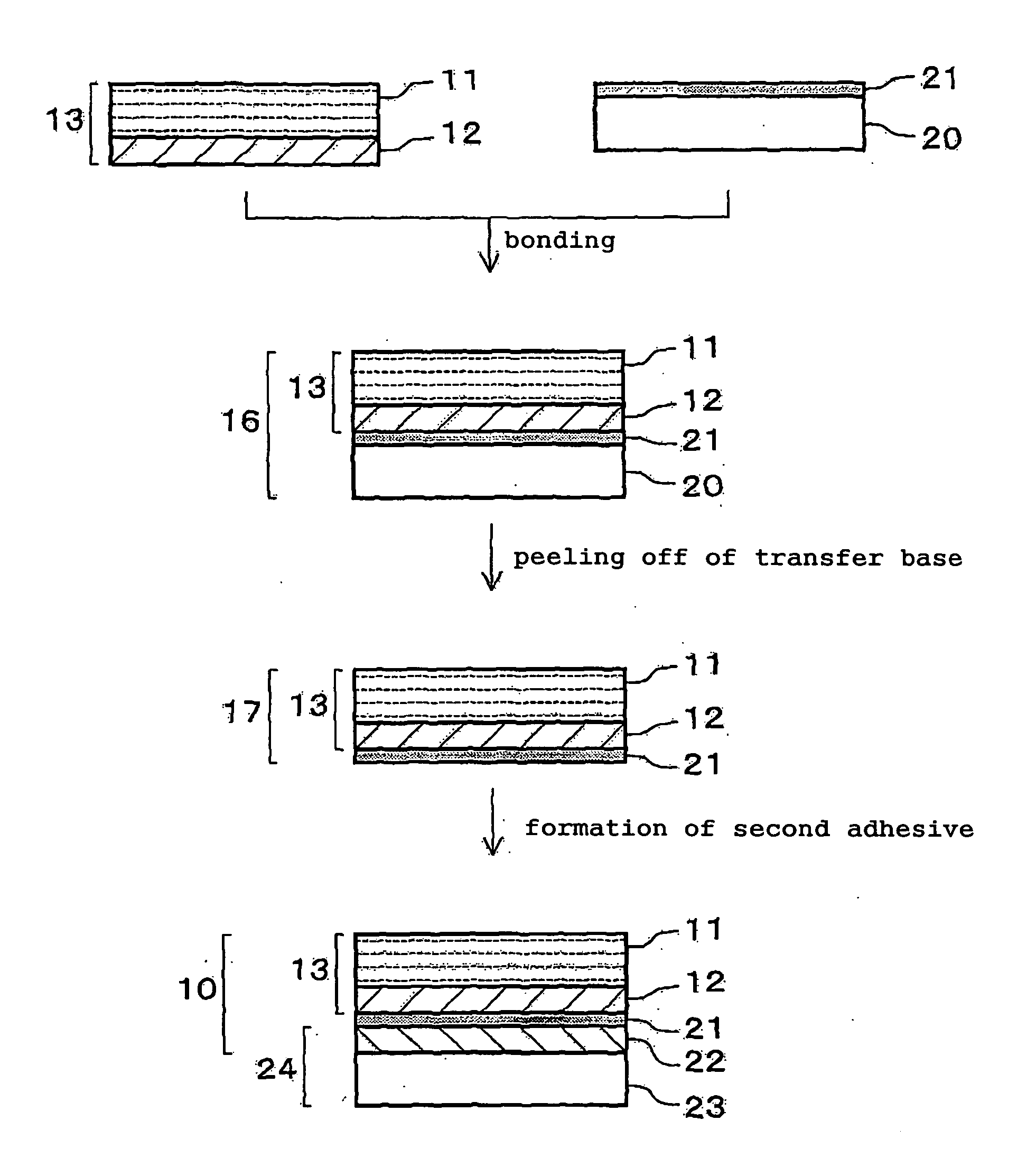
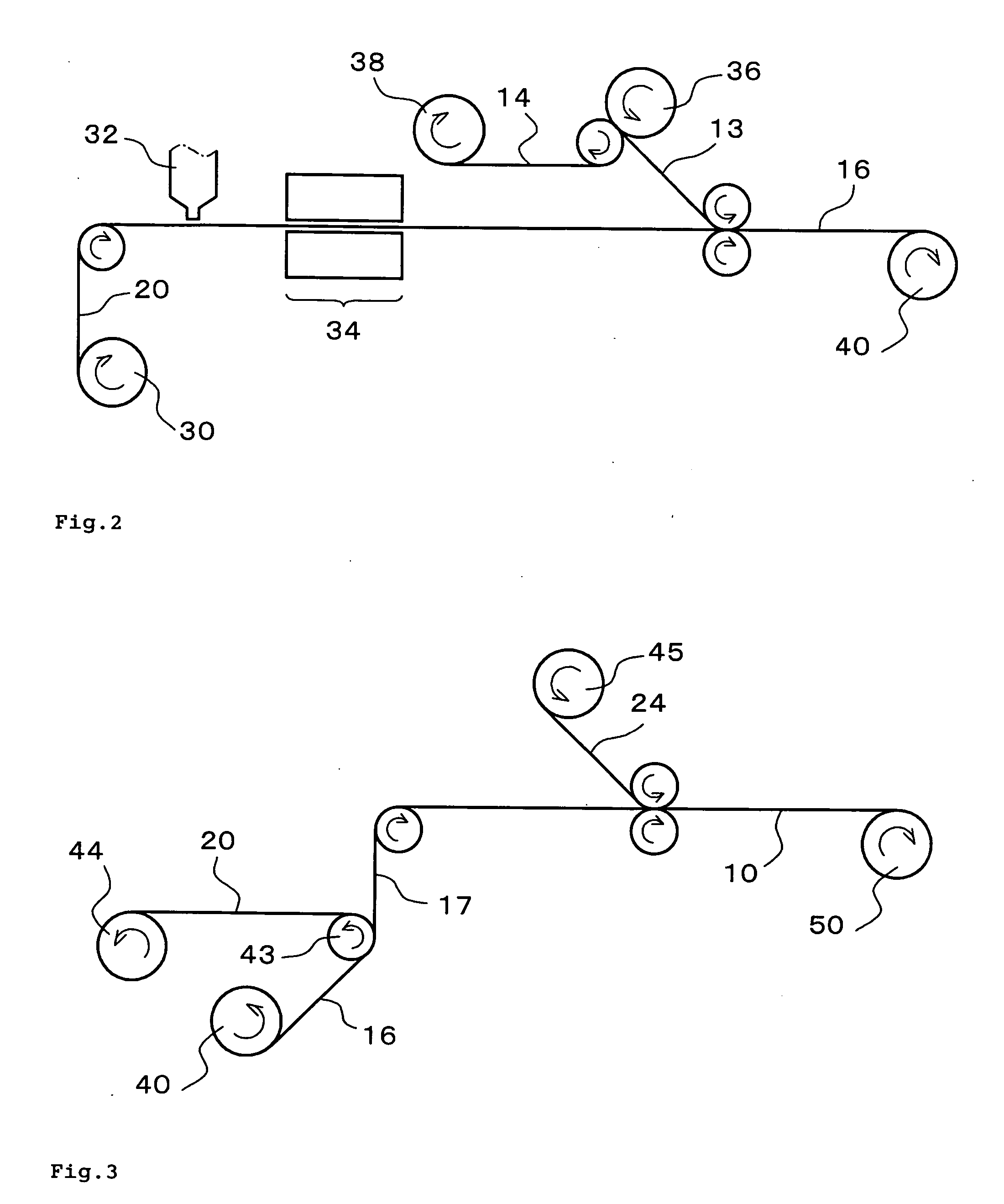
Image

Examples
example 1
[0157] A coating liquid was prepared with the following composition.
[0158] urethane resin varnish “SBU Lacquer 0866”: 16.0 parts
[0159] organic modified clay compound “Lucentite STN”: 7.2 parts
[0160] toluene: 76.8 parts
[0161] water: 0.3 parts
[0162] Undecorated synthetic hectorite was manufactured, and after that, washed with acid, and then decorated with an organic substance, and furthermore, thoroughly washed with water by the maker, and in this state, the organic modified clay compound used was gained. The amount of chlorine included in the organic modified clay compound was 1,111 ppm, and the atomic ratio of Mg / Si4 was 2.69 (values as measured by the maker). This coating liquid was filtered with a filter having a hole diameter of 1 μm after the above described composition was mixed and stirred. In this coating liquid, the solid weight ratio of the organic modified clay compound / urethane resin was 1.5 / 1 and the solid concentration was 12%. The coating liquid had a moisture rat...
PUM
| Property | Measurement | Unit |
|---|---|---|
| water contact angle | aaaaa | aaaaa |
| thickness | aaaaa | aaaaa |
| glass transition temperature | aaaaa | aaaaa |
Abstract
Description
Claims
Application Information