
System for amplifiers with low distortion and low output impedance

a low distortion and output impedance technology, applied in the field of audio signal amplification, can solve the problems of frequency response, non-feedback pwm amplifier b>150/b> can be susceptible to non-ideal electrical behavior, non-harmonic components, etc., and achieve low output impedance, low distortion amplification, and low distortion

Inactive Publication Date: 2007-03-15
TEXAS INSTR INC
View PDF6 Cites 53 Cited by
  • Summary
  • Abstract
  • Description
  • Claims
  • Application Information

AI Technical Summary

Benefits of technology

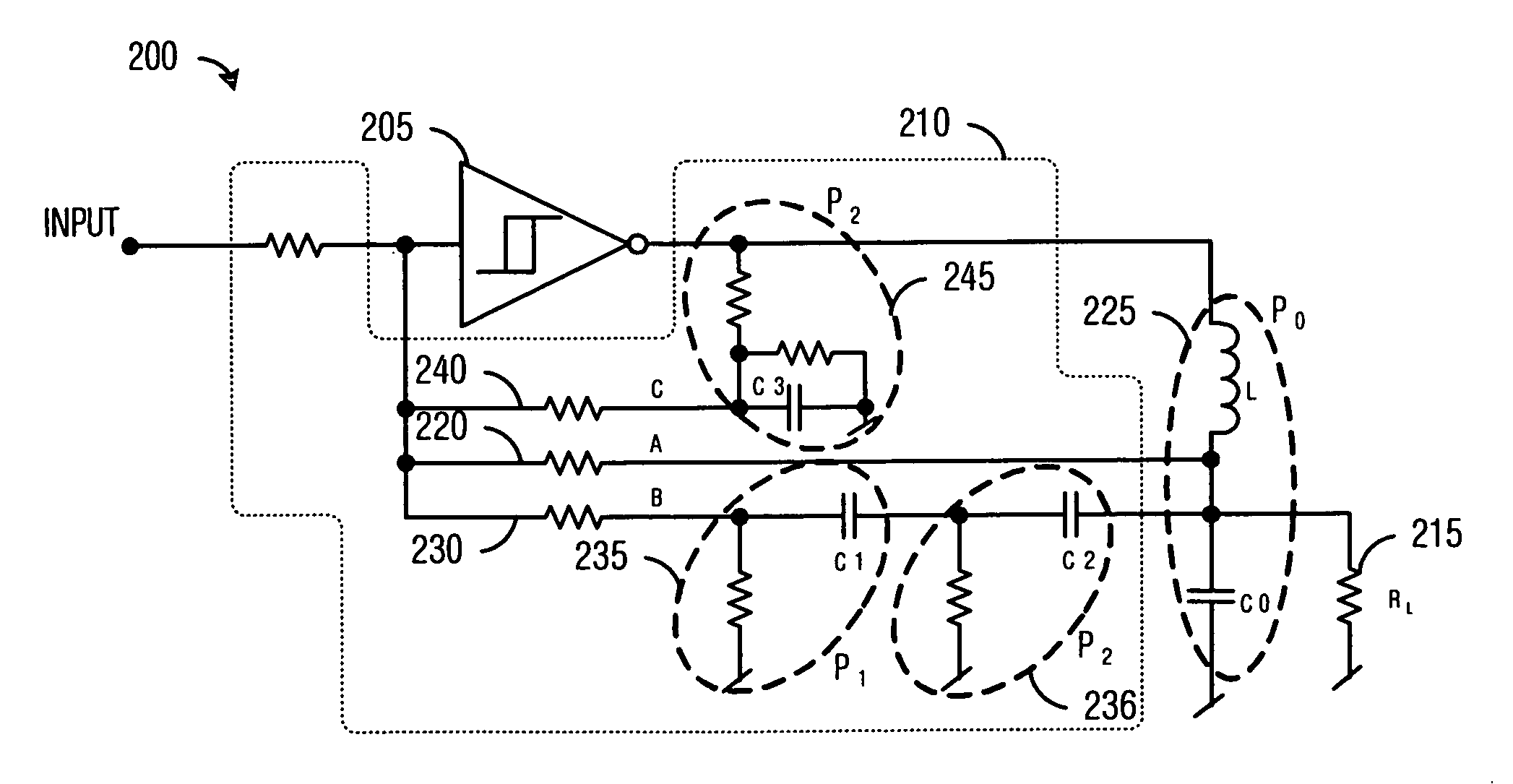
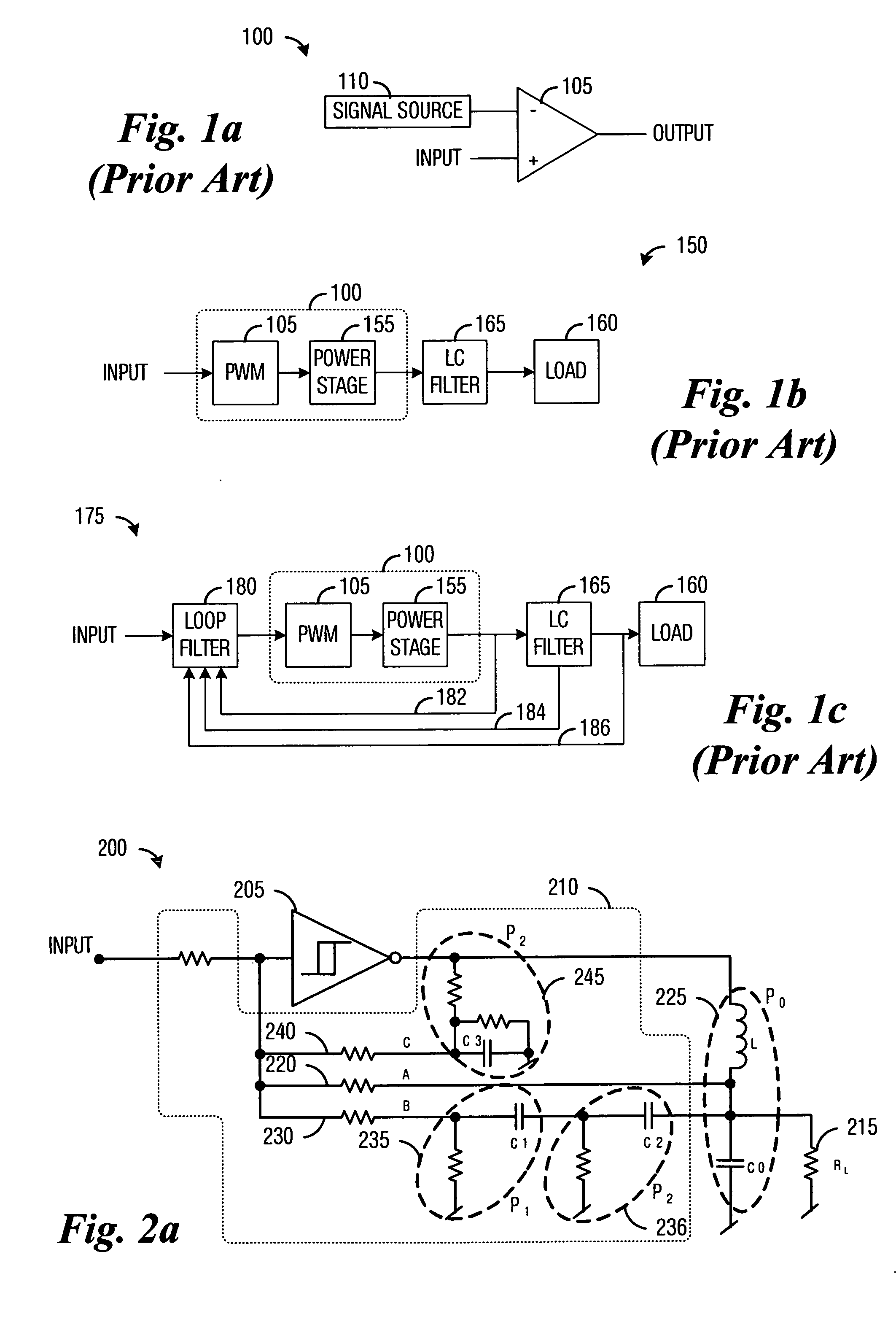
[0019] In accordance with a preferred embodiment of the present invention, an amplifier circuit is provided. The amplifier circuit includes an adder, a pulse width modulator coupled to the adder, a filter coupled to an output of the pulse width modulator, and a loop filter with a first input coupled to the output of the filter and a second input coupled to an input of the filter and an output coupled to the adder. The adder generates a difference signal responsive to an input signal and a feedback signal, the pulse width modulator compares the difference signal to a reference signal to produce a pulse width modulated signal based on the comparing, the filter having a transfer function. The loop filter generates the feedback signal by applying transfer functions to signals at its inputs, where a loop transfer function of the amplifier circuit is minimum aliasing error.
[0025] A further advantage of a preferred embodiment of the invention is that the feedback controlled PWM amplifier is stable even without load, therefore, eliminating the need for a Zobel network.

Problems solved by technology

A disadvantage of the LC filter 165 is that it has a frequency response that is a function of the load impedance, i.e., the LC filter 165 has a high output impedance that tends towards infinity at the resonant frequency of the LC filter 165.
In practice, the non-feedback PWM amplifier 150 can be susceptible to non-ideal electrical behavior, such as non-harmonic components, noise and distortion arising from switching delays, non-linearities, distortions in the carrier signal, amplitude distortion, power supply noise and ripple, and so forth.
The non-ideal electrical behavior can cause the PWM modulator 100 to introduce noise and distortion into the output signal.
However, the LC filter 165 can add a large phase delay of up to 180 degrees which can make it difficult to achieve a stable loop when the feedback is primarily taken from after the LC 165.
One disadvantage of the prior art is that the feedback loop takes its signal primarily before the LC filter 165, so the output impedance of the feedback controlled PWM amplifier 175 at high frequencies can be high.
Another disadvantage of the prior art is that a typical loop filter 180 will have active components, such as operational amplifiers, which could have slew-rate distortion.
Yet another disadvantage of the prior art is that aliasing error may not be minimized, resulting in higher than necessary distortion levels.
The aliasing error can increase the overall distortion of the feedback controlled PWM amplifier 175.
A further disadvantage of the prior art is that feedback loops that include the LC filter 165 in the loop can be unstable when the feedback controlled PWM amplifier 175 is not loaded.
However, the Zobel network will dissipate a substantial amount of power when a large amplitude audio signal is being reproduced.
This reduces the overall power efficiency of the feedback controlled PWM amplifier 175 and requires bulky components as well as protection schemes to prevent damage to the components of the Zobel network due to overheating.

Method used


Image

  • System for amplifiers with low distortion and low output impedance
  • System for amplifiers with low distortion and low output impedance
  • System for amplifiers with low distortion and low output impedance

Examples


Embodiment Construction

[0035] The making and using of the presently preferred embodiments are discussed in detail below. It should be appreciated, however, that the present invention provides many applicable inventive concepts that can be embodied in a wide variety of specific contexts. The specific embodiments discussed are merely illustrative of specific ways to make and use the invention, and do not limit the scope of the invention.

[0036] The present invention will be described with respect to preferred embodiments in a specific context, namely a class D amplifier for audio signals with low distortion and low output impedance. The invention may also be applied, however, to other types of class D amplifiers with applications in other areas, such as switching power supplies, motor control applications, non-audio signal amplifiers, and so forth.

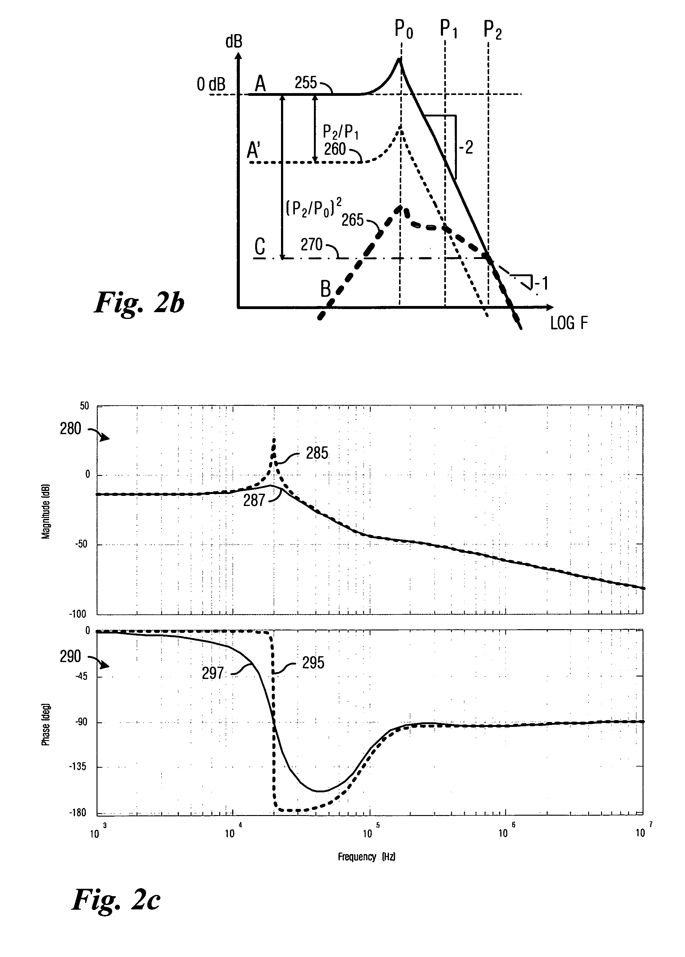
[0037] Minimum aliasing error (MAE) helps to ensure that the ripple present in the loop filter signal is as close to the ideal shape (triangular) as possible by ...


PUM


Abstract

System for pulse-width-modulated class D audio amplifiers. In one preferred embodiment an adder is described to generate a difference signal responsive to an input signal and a feedback signal, a pulse-width-modulator coupled to the adder to compare the difference signal to a reference signal and produce a pulse-width-modulated signal based on the comparing, a filter coupled to an output of the pulse-width-modulator, and a loop filter having a first input coupled to the output of the filter and a second input coupled to the input of the filter, the loop filter to generate a feedback signal by applying transfer functions to signals at its inputs. The loop transfer function of the amplifier is minimum aliasing error transfer function. The minimum aliasing error properties provide low distortion and taking the feedback from the output of the filter reduces high frequency output impedance.

Description

[0001] This application claims the benefit of U.S. Provisional Application No. 60 / 713,039, filed on Aug. 31, 2005, entitled “Passive Loop Filter for Switching Amplifiers Providing Low Distortion and Low Output Impedance,” which application is hereby incorporated herein by reference.TECHNICAL FIELD [0002] The present invention relates generally to a system for audio signal amplification, and more particularly to a system for pulse width modulated class D audio amplifiers. BACKGROUND [0003] There are several different types or classes of audio amplifiers. A class A amplifier will conduct a DC current even though there is no audio signal present at the amplifier's input. The class A amplifier will also have a single polarity voltage swing. A class B amplifier is more efficient than a class A amplifier due to the fact that both of the class B amplifier's differential mode voltage swings are not on at the same time. Class AB amplifiers maintain a small bias current through complementary ...

Claims


Application Information

Patent Timeline
Patent Type & Authority Applications(United States)
IPC IPC(8): H03F3/38
CPCH03F1/32H03F2200/351H03F3/217H03F1/34
Inventor RISBO, LARSPOULSEN, SOREN
Owner TEXAS INSTR INC
Learn More