Multi-detector edxrd

a diffraction and detector technology, applied in the field of analytical instruments, can solve the problems of low throughput and the shortcomings of the existing system of edxrd, and achieve the effects of enhanced throughput, reduced cost, and reduced cos

Active Publication Date: 2007-03-15
BRUKER TECH LTD
View PDF4 Cites 13 Cited by
  • Summary
  • Abstract
  • Description
  • Claims
  • Application Information

AI Technical Summary

Benefits of technology

[0005] Existing systems for EDXRD suffer from a number of shortcomings, among them low throughput. Embodiments of the present invention provide improved

Problems solved by technology

Existing systems for EDXRD suffer from a numb

Method used


Image

  • Multi-detector edxrd
  • Multi-detector edxrd
  • Multi-detector edxrd

Examples


Embodiment Construction

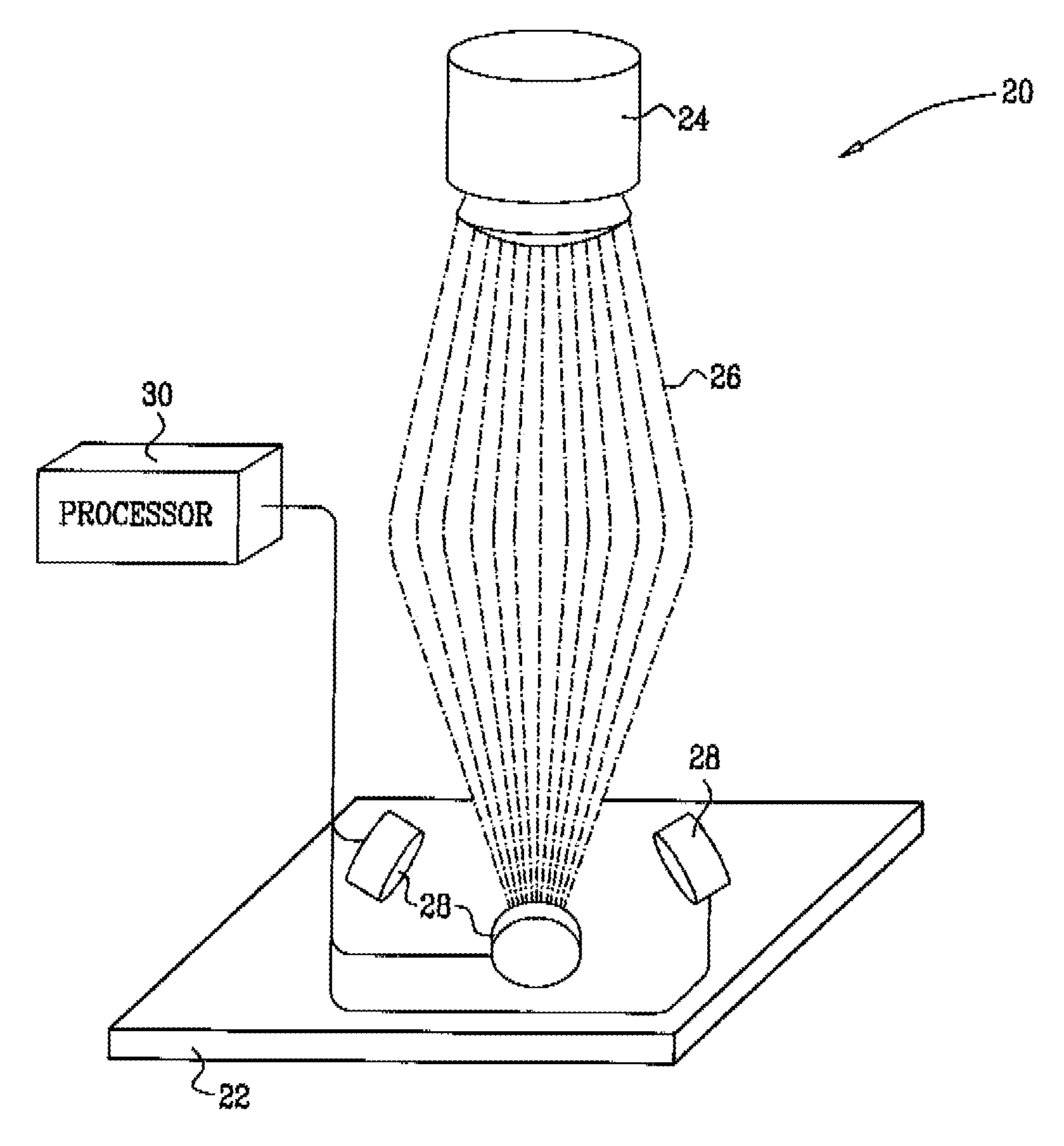
[0022]FIG. 1 is a schematic, pictorial view of a system 20 for EDXRD, in accordance with an embodiment of the present invention. In the pictured embodiment, the system is used for measurement and analysis for X-ray scattering from a thin film on the surface of a semiconductor wafer 22, but the system may likewise be applied to samples of other types. A polychromatic X-ray source 24, typically an X-ray tube, emits a beam of X-rays, which is focused to irradiate a small spot on the surface of the sample. In the present embodiment, the X-rays are focused by a monolithic polycapillary optic 26, such as those produced by X-Ray Optical Systems, Inc., of Albany, N.Y. Alternatively, other types of focusing optics may also be used, such as a monocapillary optic, a curved reflector, or pinhole optics as are known in the art.

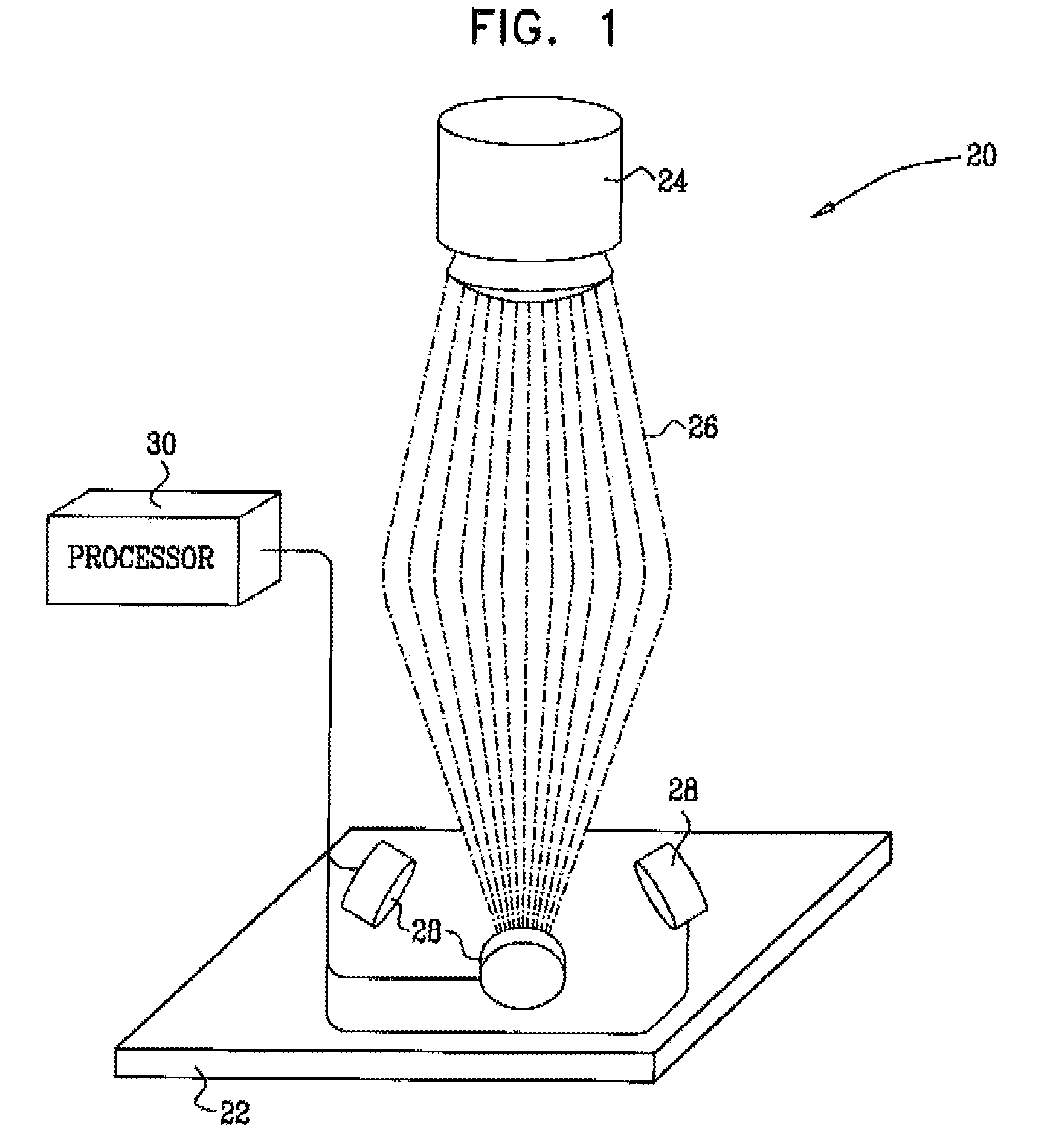
[0023] X-rays scattered from the surface of wafer 22 are captured by multiple detectors 28, which are arrayed around the polycapillary optic. A similar sort of arrangemen...


PUM


Abstract

A method for analysis of a sample includes irradiating an area of the sample with a polychromatic X-ray beam. X-rays scattered from the sample are detected using a plurality of detectors simultaneously in different, respective positions, whereby the detectors generate respective outputs. Energy-dispersive processing is applied to the outputs of the detectors so as to identify one or more X-ray diffraction lines of the sample.

Description

CROSS-REFERENCE TO RELATED APPLICATION [0001] This application claims the benefit of U.S. Provisional Patent Application 60 / 717,820, filed Sep. 15, 2005, which is incorporated herein by reference.FIELD OF THE INVENTION [0002] The present invention relates generally to analytical instruments, and specifically to instruments for measuring X-ray diffraction. BACKGROUND OF THE INVENTION [0003] Energy-dispersive X-ray diffraction (EDXRD) is known in the art as a method for measuring properties of crystalline samples. An X-ray source generates a polychromatic X-ray beam, which is incident on a sample being examined. X-rays are diffracted from the sample over a range of angles with respect to the incident beam. An energy-dispersive X-ray detector is arranged to capture the diffracted X-ray beam at a certain angle. The detector is used to measure the diffracted beam intensity as a function of photon energy, and thus to provide a spectrum of the diffracted X-rays. [0004] An exemplary EDXRD s...

Claims


Application Information

Patent Timeline
IPC IPC(8): G01N23/20
CPCG01N23/20091
Inventor YOKHIN, BORISKROKHMAL, ALEXANDERTOKAR, ALEX
Owner BRUKER TECH LTD
Why Eureka
Try Eureka