Protective film

a protective film and film technology, applied in the field of protective films, can solve the problems of insufficient anti-smudging properties, complex production process, and inability to prevent the visibility from being deteriorated, and achieve the effects of enhancing the visibility of displayed images, reducing the burden on the eyes of operators, and excellent visibility

Inactive Publication Date: 2007-03-15
FUJIFILM CORP +1
View PDF4 Cites 26 Cited by
  • Summary
  • Abstract
  • Description
  • Claims
  • Application Information

AI Technical Summary

Benefits of technology

[0026] Introduction of a surface structure has been known as another method of improving repellency. Models for the surface structure are roughly classified into two models. One model is a Wentzel model shown in FIG. 16 in which microscopic irregularities 156 are formed on the surface of a solid 154 to increase the surface area to thereby increase the contact angle.
[0032] In addition, in the Wentzel model, a straight line L shown in FIG. 17 is obtained when the surface does not have recesses, projections or other surface structure. The surface multiplication factor r in the straight line L is 1 (r=1). On the other hand, a straight line M shown in FIG. 17 is obtained when the surface has recesses, projections or other surface structure. Introduction of a surface structure to the surface increases the surface area, thereby increasing the surface multiplication factor r in the straight line M to be larger than 1 (r>1).
[0059] The protective film according to the first aspect of the invention has an uneven surface structure obtained by periodically and continuously forming recesses and projections on a fluorine-containing protective layer. The uneven surface structure satisfies the conditions of t≦390 / nb (nm) and h / t≧0.4 where t represents the period (nm), h represents the height (nm) and nb represents the refractive index of the protective layer. In this way, fluorine in the protective layer contributes to the liquid-repellent effect, whereas the uneven surface structure satisfying the above conditions has the antireflection effect. The protective film having both of the anti-smudging performance and the antireflection performance can be thus obtained.
[0060] The protective film according to the second aspect of the present invention has an uneven surface structure obtained by periodically and continuously forming recesses and projections on a supporting substrate. The uneven surface structure satisfies the conditions of t≦390 / nb (nm) and h / t≧0.4 where t represents the period (nm), h represents the height (nm) and nb represents the refractive index of the supporting substrate. Then, an anti-smudging layer made of a fluorine-containing material is formed on the supporting substrate while the uneven surface structure is maintained. In this way, the uneven surface structure satisfying the above conditions has the antireflection effects, whereas fluorine in the anti-smudging layer contributes to the liquid-repellent effect. The protective film having both of the anti-smudging performance and the antireflection performance can be thus obtained.
[0061] The protective films according to the first and second aspects of the present invention have both of the anti-smudging performance and antireflection performance, so outside light or fluorescent light of a fluorescent lamp reflected on the display surface is reduced. Therefore, the visibility of displayed images is enhanced while the burden on the eyes of an operator can be reduced. In addition, fingerprints, sebum, sweat, cosmetics and the like are not readily adhered to the protective film and even if fingerprints, sebum, sweat, cosmetics and the like are adhered, they are readily removed. Accordingly, in the case where a display screen of any of various monitors or a touch panel display screen is provided with the protective film, excellent visibility, high resistance to smudging and easy removal of smudges are achieved to prevent the visibility from being reduced by smudges while the operation for smudge removal can be simplified owing to the high resistance to smudging. The protective film can be thus appropriately attached to the display screen of any of various unmanned monitors or the touch panel display screen.

Problems solved by technology

The anti-smudge agent in JP 2000-144097 A is thus disadvantageous in that it does not have sufficiently high anti-smudging properties against oil that constitutes the principle component of smudges.
JP 11-64602 A is disadvantageous in that the wavelength range within which reflection can be prevented is narrow and the production process is complicated because the film is of a multilayer structure.
Therefore, when the techniques in these documents are applied to touch panels, there is posed a problem that their visibility is not prevented from being deteriorated by adhesion of fingerprints, sebum, sweat, cosmetics and the like due to touching with a finger.

Method used


Image

  • Protective film
  • Protective film
  • Protective film

Examples


first embodiment

[0136] [First embodiment]

[0137]FIG. 10A is a schematic sectional view showing a protective film according to a first embodiment of the present invention, and Fig. 10B is a schematic plan view of the protective film shown in FIG. 10A.

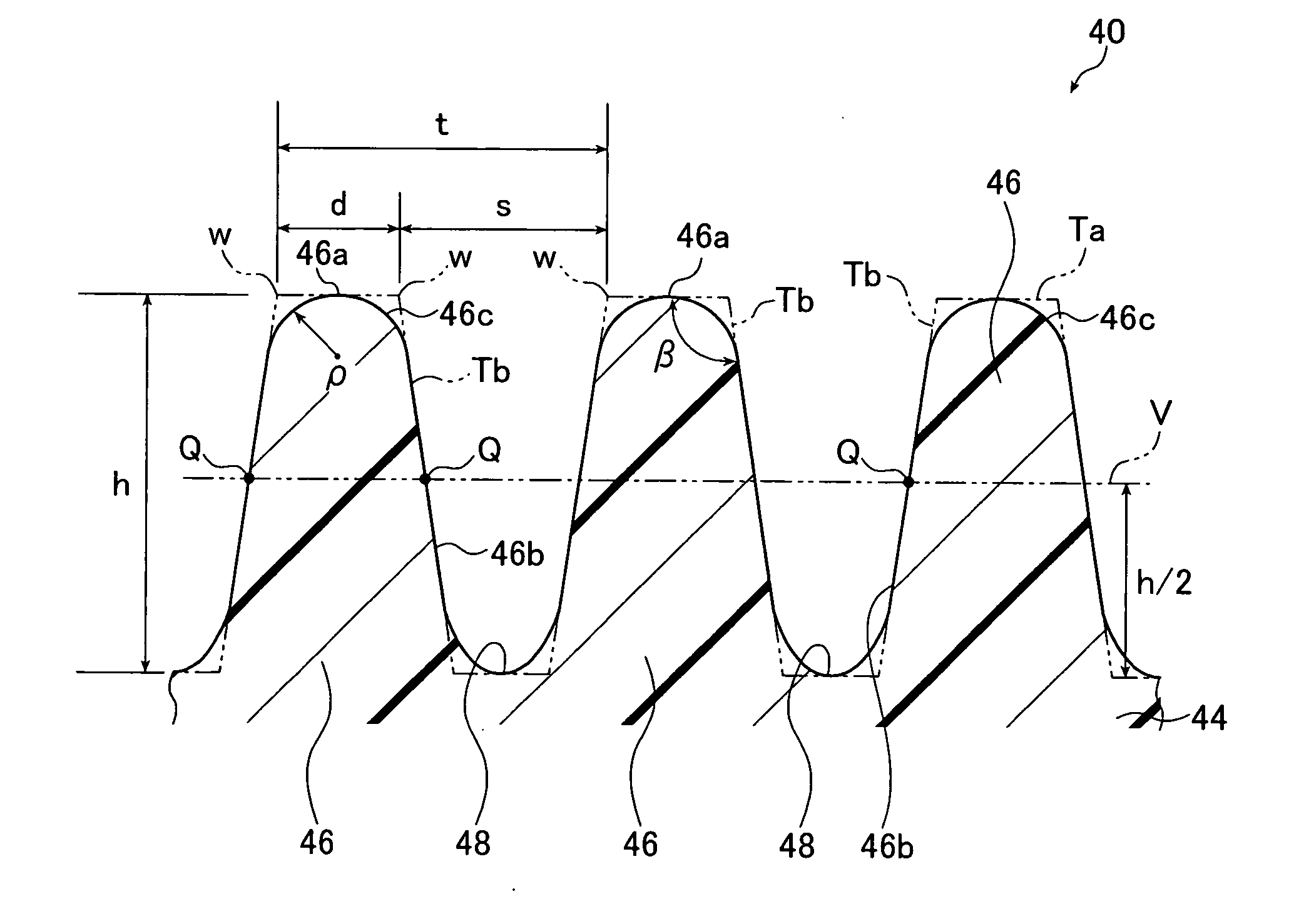
[0138] As shown in FIG. 10A, a protective film 40 in this embodiment includes a supporting substrate 42 and a protective layer 44 formed on a surface of the supporting substrate 42.

[0139] The supporting substrate 42 supports the protective layer 44 and its surface is flat. The supporting substrate 42 is formed from, for example, a plastic film that is transparent in a visible light wavelength range of 380 nm to 630 nm.

[0140] The plastic film that may be used for the supporting substrate 42 is preferably formed of, for example, cellulose ethers such as triacetyl cellulose, diacetyl cellulose and propionyl cellulose or polyolefins such as polypropylene, polyethylene and polymethylpentene.

[0141] The protective layer 44 is a nonreflective, anti-smudging ...

second embodiment

[0166] [Second embodiment]

[0167] Next, a protective film according to a second embodiment of the present invention will be described. In this embodiment, the same components as those in the first embodiment shown in FIGS. 10A, 10B and 11 are denoted by the same reference numerals and their detailed description will be omitted.

[0168]FIG. 12A is a schematic sectional view showing the protective film according to the second embodiment of the present invention, and FIG. 12B is a schematic plan view of the protective film shown in FIG. 12A. FIG. 13 is a sectional view taken along the line II-II in FIG. 12B.

[0169] As shown in FIG. 12A, the protective film 50 in this embodiment is different from the protective film 40 in the first embodiment (see FIG. 10A) in the structure of the protective layer 52 but the former is the same as the latter in the structures of the other portions, so their detailed description will be omitted.

[0170] As shown in FIGS. 12A and 12B, the protective layer 52 ...

third embodiment

[0186] [Third embodiment]

[0187] Next, a protective film 60 according to a third embodiment of the present invention will be described. In this embodiment, the same components as those in the first embodiment shown in FIGS. 10A, 10B and 11 are denoted by the same reference numerals and their detailed description will be omitted.

[0188]FIG. 14 is a schematic sectional view showing the protective film according to the third embodiment of the present invention.

[0189] As shown in FIG. 14, the protective film 60 of this embodiment is the same as the protective film 40 of the first embodiment (see FIG. 10A) except that the protective layer 44 is not formed but projections 64 and recesses 66 are formed on a supporting substrate 62 that is transparent in the visible light region, and that an anti-smudging layer 68 is formed on the projections 64 and the recesses 66 of the supporting substrate 62, so its detailed description will be omitted.

[0190] For example, cellulose ethers such as triac...


PUM

PropertyMeasurementUnit
refractive indexaaaaaaaaaa
contact angleaaaaaaaaaa

Abstract

The protective film includes a transparent supporting substrate, and a protective layer that is formed on a surface of the supporting substrate and contains fluorine. The protective layer has an uneven surface structure obtained by periodically and continuously forming recesses and projections and the uneven surface structure satisfies relations of t≦390 / nb (nm) and h / t ≦0.4. Herein, t represents a period (nm) of the uneven surface structure, h represents a height (nm) which is a distance between a top of each of the projections and a bottom of each of the recesses, and nb represents a refractive index of the protective layer.

Description

BACKGROUND OF THE INVENTION [0001] The present invention relates to a protective film having both of antireflection function and anti-smudging function, and more specifically a protective film that is used in liquid crystal display panels or other display devices, protects their display screens against smudges and at a time achieves reduction of light reflected from the display screens. [0002] Nowadays, flat panel displays (FPDs) are mainly employed for the display devices along with the popularization of liquid crystal displays and plasma displays. [0003] Touch panels whose display screens are directly touched with a finger or a pen to perform device operation are increasingly used as in automatic teller machines (ATMs) or Tablet PCs of the pen-based input type. [0004] In order to operate a device, such a touch panel is provided with a detector for detecting the operation that is made on the surface of the display screen. The detector is, for example, a conductive sheet which detec...

Claims


Application Information

Patent Timeline
Patent Type & Authority Applications(United States)
IPC IPC(8): G11B5/64
CPCG02B1/105G02F1/13338Y10T428/24355G02F2201/50G02F1/133502G02B1/18G02B1/14
Inventor KANEKO, YASUHISA
Owner FUJIFILM CORP
Why Eureka
Try Eureka