Method of measuring hematocrit (hct), sensor used in the method, and measuring device

a technology of hematocrit and sensor, applied in the field of method of measuring hct, sensor used in the method, and measuring device, can solve the problems of long time, complicated operation, and difficulty in using a sensor, and achieve excellent measurement accuracy, high sensitivity, and easy measurement.

Active Publication Date: 2007-03-22
PHC HLDG CORP
View PDF35 Cites 39 Cited by
  • Summary
  • Abstract
  • Description
  • Claims
  • Application Information

AI Technical Summary

Benefits of technology

[0008] As described above, in the measurement method and the sensor of the present invention, the redox substance is provided on the counter electrode but not on the working electrode in the electrode system having the working electrode and the counter electrode. Thus, blood containing no redox substance is present on the working electrode. Therefore, according to the present invention, a reliable current value that depends on the Hct value of blood can be obtained by the working electrode, and this current value can be detected with high sensitivity by the redox substance on the counter electrode. As a result, the measurement can be carried out easily with excellent measurement accuracy. Moreover, the present invention can realize electrochemical measurement of a Hct value using a sensor, which eliminates the necessity of using a special large-scale measuring instrument or device as in the conventional measurement methods.

Problems solved by technology

However, the conventional method for carrying out the manual Hct measurement has a problem in that it requires complicated operations and takes a long time.
On the other hand, the Hct measurement method using an automatic blood cell counter has a problem in that it is necessary to use a special device.
However, the conventional method of measuring a Hct value using a sensor has a problem in its accuracy and reliability.

Method used


Image

  • Method of measuring hematocrit (hct), sensor used in the method, and measuring device
  • Method of measuring hematocrit (hct), sensor used in the method, and measuring device
  • Method of measuring hematocrit (hct), sensor used in the method, and measuring device

Examples


example 1

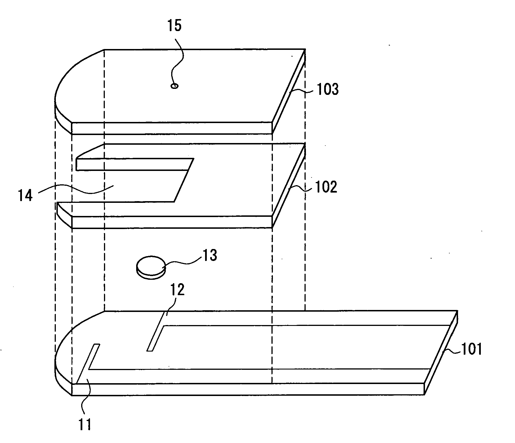
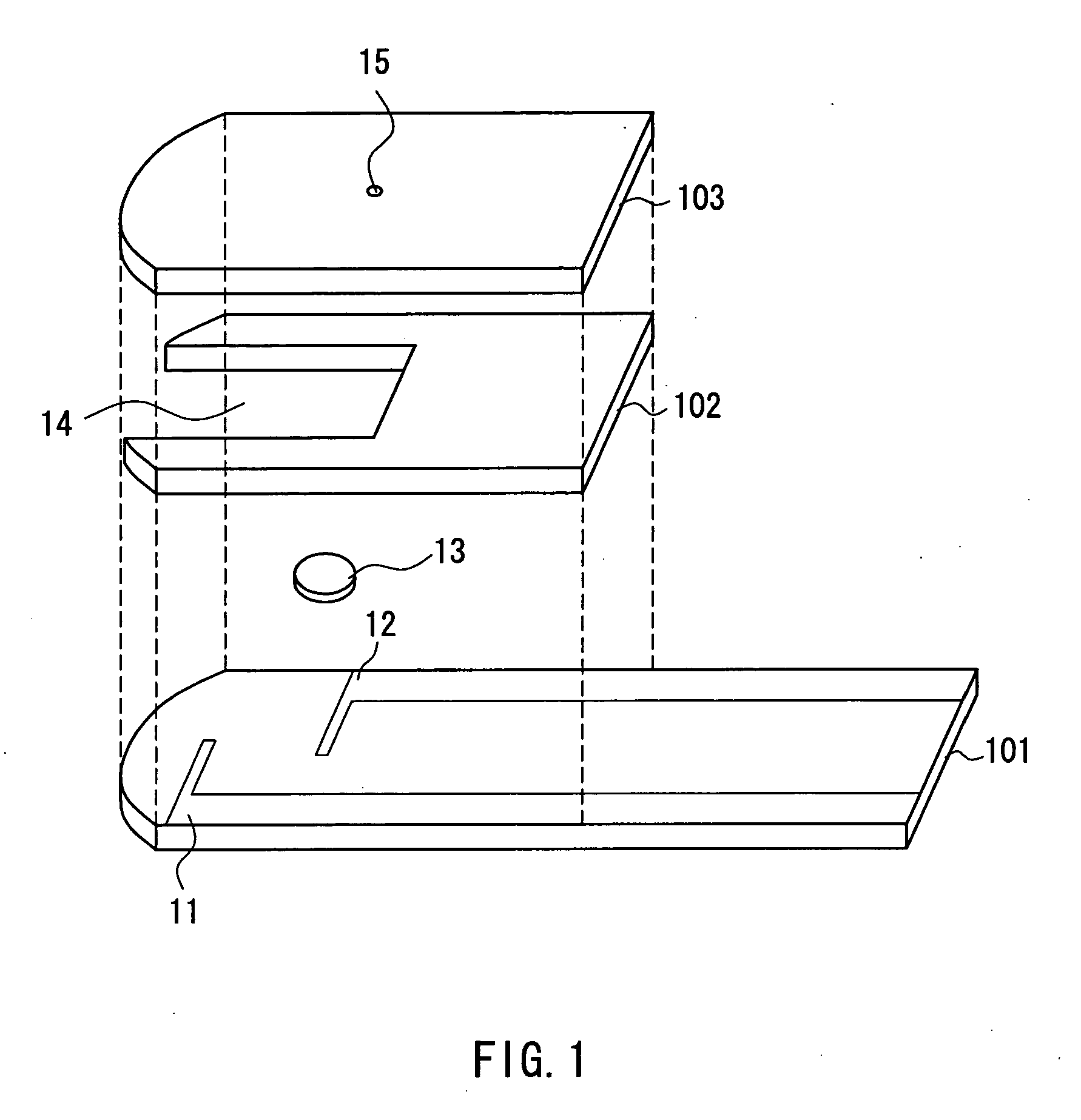
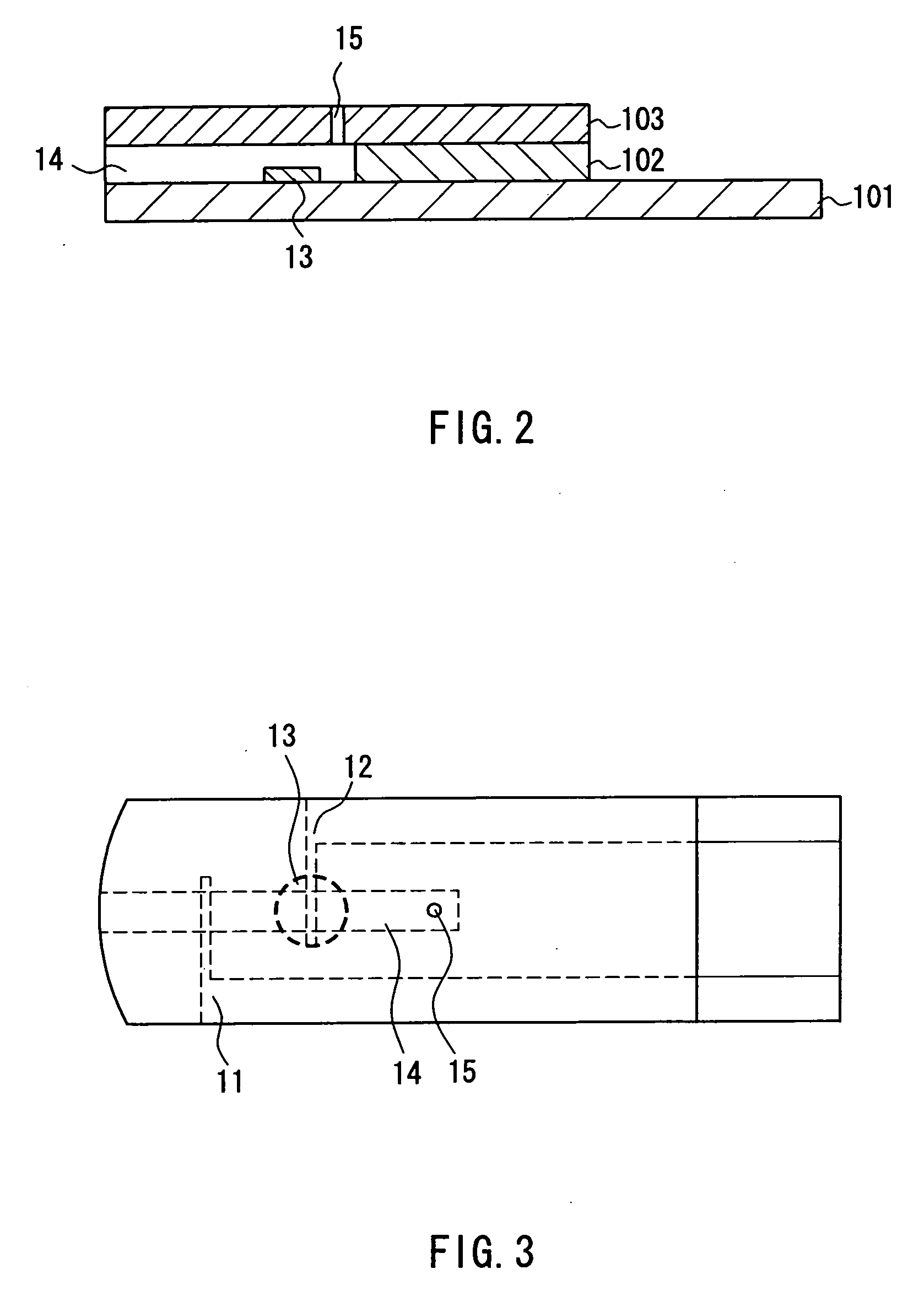
[0071] A sensor having a configuration as shown in FIGS. 1, 2, and 3 was produced. In this sensor, a working electrode 11 was coated with CMC. On the other hand, a reagent solution prepared by dissolving potassium ferricyanide (amount: 60 mM) and taurine (80 mM) in a CMC aqueous solution (0.1 wt %) was dropped on a counter electrode 12 and then dried. The shortest distance between the electrodes was set to be at least 1.0 mm. On the other hand, three types of blood samples whose Hct values were adjusted so as to be 25, 45, and 65, respectively, were provided. With regard to each of these three blood samples, a current flowing between the electrodes of the sensor when a voltage of 2.5 V was applied for 3 seconds was measured using the sensor. The results are shown in the graphs of FIGS. 7A and 7B. FIG. 7A is a graph showing changes in response current (μA) over time during the application of the voltage (V), and FIG. 7B is a graph showing changes in difference in sensitivity (%) over...

example 2

[0074] In the present example, six types of sensors (2-1 to 2-6) were produced so that they were different from each other in the arrangement of a redox substance (potassium ferricyanide) with respect to a working electrode or a counter electrode, and the response current and the difference in sensitivity were measured using these sensors. Also, as sensors according to Comparative Example 3, three types of sensors (2-7 to 2-9) were produced so that they were different from each other in the arrangement of a redox substance (potassium ferricyanide) with respect to a working electrode or a counter electrode, and the response current and the difference in sensitivity were measured using these sensors. Note here that the above-described respective sensors were produced in the same manner as in Example 1 except for the arrangement of the redox substance and the distance between the electrodes (1.15 mm). Also note that the response current and the difference in sensitivity were measured i...

example 3

[0093] In the present example, the response current and the difference in sensitivity of a sensor were measured at various applied voltages in the range from 0.5 to 6.5 V. The sensor was produced in the same manner as in Example 1. Furthermore, the response current and the difference in sensitivity were measured in the same manner as in Example 1. The results of the measurement are shown in the graphs of FIGS. 19 to 31. In FIG. 19 to FIG. 31, FIGS. 19A to 31A are graphs each showing changes in response current (A) over time during the application of the voltage (V), and FIGS. 19B to 31B are graphs each showing changes in difference in sensitivity (%) over time during the application of the voltage (V).

[0094] As shown in FIG. 19, even when the applied voltage was 0.5 V, it was possible to detect the response current reflecting the Hct value. However, as shown in FIGS. 20 to 31, the response current could be measured still more definitely when the applied voltage was in the range fro...


PUM

PropertyMeasurementUnit
applied voltageaaaaaaaaaa
distanceaaaaaaaaaa

Abstract

The present invention provides a method of electrochemically measuring a hematocrit (Hct) value using a sensor, capable of achieving excellent measurement accuracy and reliability and also provides a sensor used in the method. The method of electrochemically measuring a hematocrit (Hct) value of blood include: providing an electrode system having a working electrode (11) and a counter electrode (12), in which a redox substance is provided on the counter electrode (12) but not on the working electrode (11); supplying blood to the electrode system; applying a voltage to the electrode system in this state to cause an oxidation current or a reduction current to flow between the working electrode (11) and the counter electrode (12); detecting the oxidation current or the reduction current; and determining a Hct value based on a value of the detected current.

Description

TECHNICAL FIELD [0001] The present invention relates to a method of measuring a Hct, a sensor used in the method, and a measuring device. BACKGROUND ART [0002] In clinical tests and the like, the Hct value of blood is measured as one index that helps to know properties of the blood (flowability, whether or not the subject has anemia, etc.). Furthermore, in blood component measurement such as measurement of a glucose concentration (a blood glucose level) in blood, a measured value may vary depending on a Hct value, so that the measurement of the Hct value might be required in order to correct the measured value. In general, the manual measurement of a Hct value is carried out, for example, by adding a blood coagulation inhibitor to blood, causing the blood to be drawn into a capillary tube, sealing one end of the tube with putty or the like, subjecting the tube to high speed centrifugation, and then determining the ratio of red blood cells to the blood as a whole as 100%, based on th...

Claims


Application Information

Patent Timeline
Patent Type & Authority Applications(United States)
IPC IPC(8): G01F1/64G01N33/487
CPCG01N27/3274G01N27/327G01N33/487G01N33/49
Inventor FUJIWARA, MASAKISHINNO, TEPPEIIKEDA, SHIN
Owner PHC HLDG CORP
Why Eureka
Try Eureka