Radial power divider/combiner using waveguide impedance transformers

a technology of waveguide impedance transformer and power divider, which is applied in the direction of amplifiers, amplifiers with semiconductor devices/discharge tubes, amplifiers, etc., can solve the problems of high power consumption, high cost, and high power consumption, and achieve high precision, low cost, and mass production

Inactive Publication Date: 2007-03-22
L 3 COMM CORP
View PDF31 Cites 27 Cited by
  • Summary
  • Abstract
  • Description
  • Claims
  • Application Information

AI Technical Summary

Benefits of technology

[0008] A radial power divider / combiner according to the invention is not only low-loss, but also broadband. Because simple milling technology may be used to fabricate the divider / combiner, it can be mass produced with high precision and low cost.

Problems solved by technology

Because a single amplifier chip cannot achieve this level of power without incurring excessive size and power consumption, modern SSPA designs typically use a radial splitting and combining architecture in which the signal is divided into a number of individual parts.
Additionally, a typical power-combiner, such as the in-phase Wilkinson combiner or the 90-degree branch-line hybrid, in which a number of binary combiners are cascaded, becomes very lossy and cumbersome when the number of combined amplifiers becomes large.
Such losses are unacceptable for most applications.
The stripline radial combiner, using multi-section impedance transformers and isolation resistors, still suffers excessive loss at Ka-band, mainly because of the extremely thin substrate (<10 mil) required at Ka-band.
The coaxial waveguide approach uses oversized coaxial cable, which introduces moding problems and, consequently, is useful only at low frequencies.
The field distribution of a regular feed horn is not uniform, however, with more energy concentrated near the beam center.
To make field distribution uniform, these waveguide feed horns require sophisticated dielectric loading and, consequently, become very large and cumbersome.

Method used


Image

  • Radial power divider/combiner using waveguide impedance transformers
  • Radial power divider/combiner using waveguide impedance transformers
  • Radial power divider/combiner using waveguide impedance transformers

Examples


Embodiment Construction

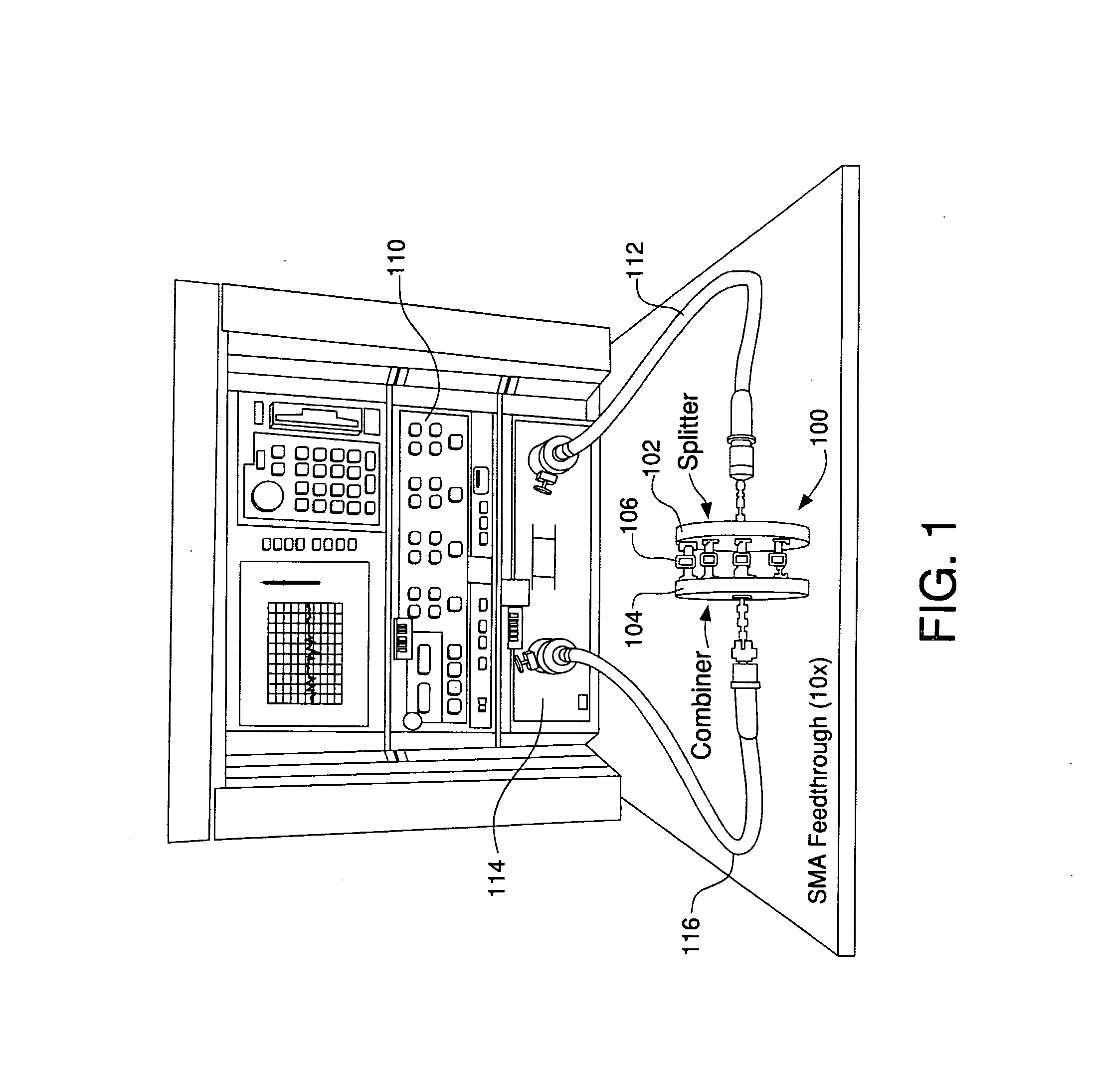
[0027]FIG. 1 depicts an example embodiment of a radial divider-combiner 100 according to the invention. As shown, the radial divider-combiner 100 includes a divider 102 and a combiner 104. A signal generator 110 provides to the divider 102 an input signal having an amplitude and frequency. The input signal may or may not be modulated. As shown, the signal generator 110 may be a test device or simulator, for example, that provides the input signal to the divider 102 via a coaxial cable 112. In operation, the signal generator 110 may be any device that provides a signal to the radial divider-combiner 100. The coaxial cable 112 may be attached to the divider 102 via a connector, such as an SMA connector, for example.

[0028] Inside the divider 102, the input signal is divided into a plurality, N, of individual signals. Each individual signal has roughly the same amplitude and frequency as the input signal. The individual signals are provided to respective amplifiers 106. The amplifiers ...


PUM


Abstract

A radial power divider-combiner is disclosed. Such a radial divider-combiner may include a plurality of waveguides, each of which extends between a central monopole antenna and a respective peripheral monopole antenna. Such a waveguide may have a central portion with a height-to-width ratio of two, and a peripheral portion having an aspect ratio of one. To improve impedance-matching, a transformer portion may be disposed between the central portion and the peripheral portion. Such a transformer portion may have any number of sections, from one to infinity, with each section having a respective height between that of the central portion and that of the peripheral portion. In the extreme case, where the number of “sections” is infinite, the height of the transformer portion may vary linearly from that of the central portion and that of the peripheral portion.

Description

CROSS-REFERENCE TO RELATED APPLICATIONS [0001] This application is a continuation-in-part of U.S. patent application Ser. No. 11 / 509,160, filed Aug. 24, 2006, which is a continuation of U.S. patent application Ser. No. 11 / 241,002, filed Sep. 30, 2005, now U.S. Pat. No. 7,113,056, which is a continuation of U.S. patent application Ser. No. 10 / 773,947, filed Feb. 6, 2004, now U.S. Pat. No. 6,982,613. The disclosures of each of the above-referenced U.S. patent applications are incorporated herein by reference.FIELD OF THE INVENTION [0002] Generally, the invention relates to radial power divider / combiners. In particular, the invention relates to radial power divider / combiners that use waveguide impedance transformers and are suitable for use in solid-state power-amplifier modules. BACKGROUND OF THE INVENTION [0003] Solid-state power-amplifier modules (SSPAs) have a variety of uses. For example, SSPAs may be used in satellites to amplify severely attenuated ground transmissions to a leve...

Claims


Application Information

Patent Timeline
Patent Type & Authority Applications(United States)
IPC IPC(8): H01P5/12
CPCH01P5/12H01P5/02
Inventor WU, YOU-SUNSMITH, MARK FRANCISREMER, JAMES NORMAN
Owner L 3 COMM CORP
Why Eureka
Try Eureka