Optical tomographic imaging apparatus

a tomographic imaging and optical fiber technology, applied in the field of optical tomographic imaging apparatus, can solve the problems of degrading depth direction resolution, affecting image quality, and affecting image quality, so as to and prevent image quality degradation due to wavelength dispersion of optical fiber

Inactive Publication Date: 2007-03-22
FUJI PHOTO OPTICAL CO LTD
View PDF9 Cites 16 Cited by
  • Summary
  • Abstract
  • Description
  • Claims
  • Application Information

AI Technical Summary

Benefits of technology

[0024] The optical tomographic imaging apparatus of the present invention includes: a probe having an optical fiber for guiding measuring light split by a light splitting means, and a dispersion compensating means for compensating for the wavelength dispersion caused by the optical fiber of the probe. Therefore, even in a case where an optical fiber is required in order to obtain a tomographic image inside of a body cavity, the wavelength dispersion caused by the optical fiber is compensated by the dispersion compensating means, so that image quality degradation due to wavelength dispersion of the optical fiber may be prevented.
[0025] If a configuration is adopted in which the optical path length control means controls the optical path length of reference light and includes: a diffraction grating element for spectrally dispersing the reference light; a collimator lens for collimating the reference light dispersed by the diffraction grating element; and a reflection mirror for reflecting the reference light collimated by the collimating lens back to the collimator lens, and a dispersion compensating means is formed by tilting the diffraction grating element with respect to the optical axis of the collimator lens, then the optical path length control means for controlling the optical path length of the reference light required for OCT measuring may also have the dispersion compensating function, so that the dispersion compensation may be implemented by a simple structure without requiring additional structures.
[0026] Further, even when a configuration is adopted in which the light source unit outputs low coherent light, and the depth position to be measured is changed according to the pivoting of the reflection mirror, the wavelength dispersion of the optical fiber is compensated by the dispersion compensating means, so that the image quality degradation due to the wavelength dispersion of the optical fiber may be prevented.
[0027] Still further, even when a configuration is adopted in which the light source unit outputs laser light by varying the wavelength at a predetermined period; the interference light detecting means detects the intensity of the reflected light reflected from the depth position of a measuring object based on the frequency and intensity of the interference light; and the optical path length control means changes the depth position of the measuring object to be measured according to the pivoting of the reflection mirror, the wavelength dispersion of the optical fiber is compensated by the dispersion compensating means, so that the image quality degradation due to the wavelength dispersion of the optical fiber may be prevented.
[0028] Further, even when a configuration is adopted in which the light source unit outputs low coherence light; the interference light detecting means detects the intensity of the reflected light reflected from each depth position of a measuring object based on the frequency and intensity of the interference light; and the optical path length control means changes the depth position of the measuring object to be measured according to the pivoting of the reflection mirror, the wavelength dispersion of the optical fiber is compensated by the dispersion compensating means, so that the image quality degradation due to the wavelength dispersion of the optical fiber may be prevented.

Problems solved by technology

When the broadband light is guided through the optical fiber, however, the dispersion of the light becomes significant due to the dispersion properties of the optical fiber.
This causes a problem that the resolution in the depth direction is degraded.
Further, even if the OCT measuring is structured in the bulk type, there is no other way than to use an optical fiber for guiding the measuring light when obtaining a tomographic image inside of the body cavity.
That is, when obtaining a tomographic image by inserting the probe into the body cavity, the image is degraded due to the dispersion properties of the optical fiber of the probe.

Method used


Image

  • Optical tomographic imaging apparatus
  • Optical tomographic imaging apparatus
  • Optical tomographic imaging apparatus

Examples


Embodiment Construction

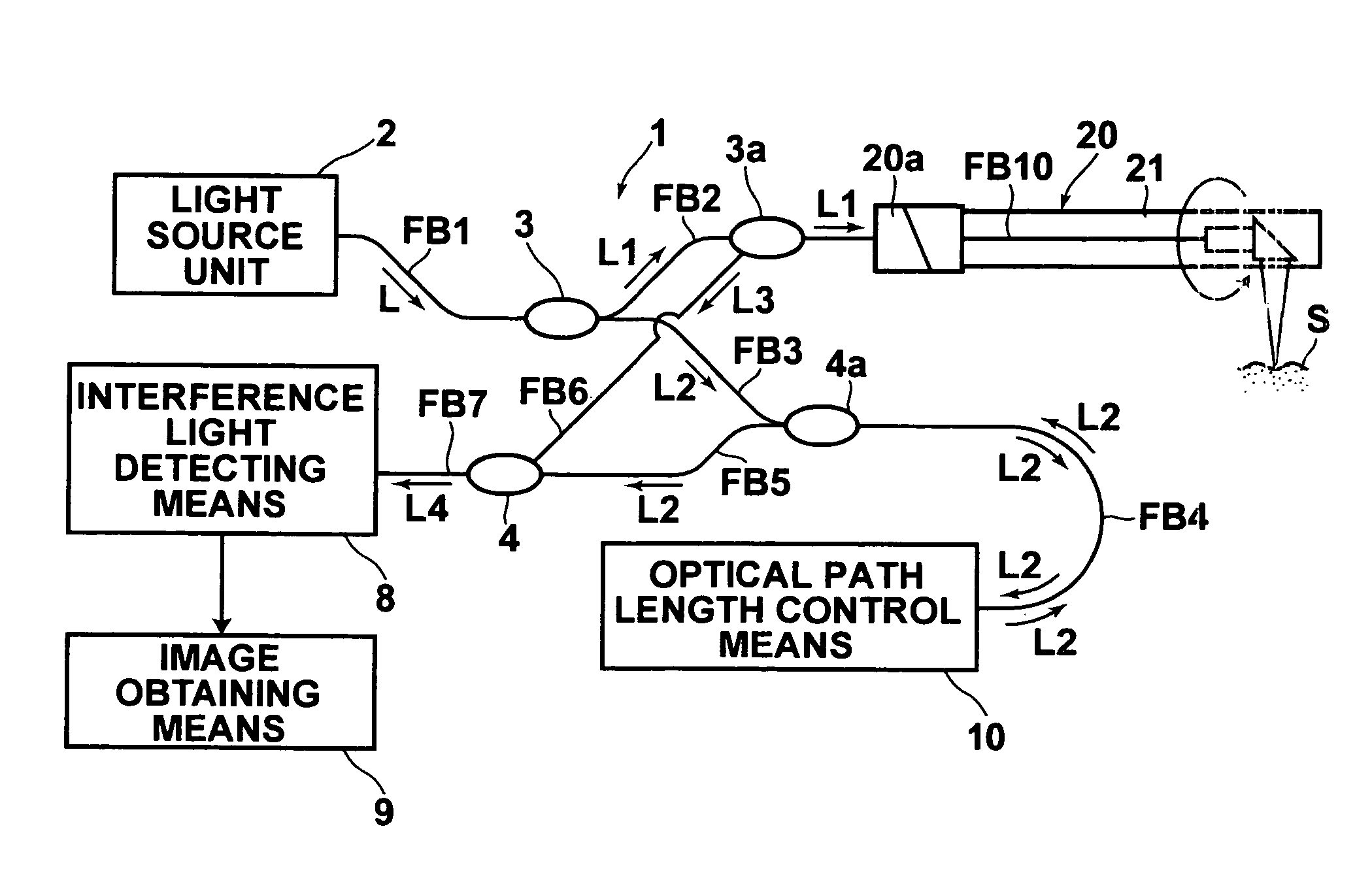
[0037] Hereinafter, exemplary embodiments of the optical tomographic imaging apparatus of the present invention will be described in detail with reference to the accompanying drawings. FIG. 1 is a construction diagram of a first embodiment of the optical tomographic imaging apparatus of the present invention. The optical tomographic imaging apparatus 1 is an apparatus for obtaining a tomographic image by so-called TD-OCT (Time Domain Optical Coherence Tomography) measuring. It includes: a light source unit 2 for outputting light; a light splitting means 3 for splitting the light outputted from the light source unit 2 into measuring light L1 and reference light L2; a light combining means 4 for combining reflected light L3 and the reference light L2; an interference light detecting means 8 for detecting interference light L4 produced when the reflected light L3 is combined with the reference light L2 by the light combining means 4; and an image obtaining means 9 for obtaining an opti...


PUM


Abstract

OCT measuring that uses an optical fiber and is capable of preventing degradation in the resolution due to the wavelength dispersion of the optical fiber. For controlling the optical path length of the reference light in the OCT measuring, the following are provided: a diffraction grating element for dispersing the reference light; a collimator lens for collimating the dispersed reference light; and a reflection mirror for reflecting the reference light transmitted through the collimator lens back to the collimator lens and inputting to the diffraction grating element. The reflection mirror pivots on a position offset from the optical axis of the collimator lens. The diffraction grating element is tilted with respect to the optical axis of the collimator lens to compensate for the wavelength dispersion of the optical fiber.

Description

BACKGROUND OF THE INVENTION [0001] 1. Field of the Invention [0002] The present invention relates to an optical tomographic imaging apparatus for obtaining a tomgraphic image of a measuring object. In particular, the present invention relates to an optical tomographic imaging apparatus suited for obtaining a tomographic image of a measuring object such as a living tissue in a body cavity or the like. [0003] 2. Description of the Related Art [0004] Electronic endoscope apparatuses are spread widely and used in various fields as the endoscope apparatus for observing inside of the cavity of a living body. The electronic apparatus obtains an image of a living body using reflected light reflected from the living body illuminated by illumination light and displays it on the monitor. Most of the endoscope apparatuses have a mouth forceps to allow a probe to be introduced inside of the body cavity through the forceps channel to perform a biopsy or treatment of the tissue within the cavity. ...

Claims


Application Information

Patent Timeline
Patent Type & Authority Applications(United States)
IPC IPC(8): G01B9/02
CPCG02B21/0056G01B9/02058G01B9/02091G01B2290/35
Inventor FUJITA, HIROSHI
Owner FUJI PHOTO OPTICAL CO LTD
Why Eureka
Try Eureka