
Lighting system and back-light device using this lighting system

Inactive Publication Date: 2007-03-22
SONY CORP
View PDF8 Cites 45 Cited by
  • Summary
  • Abstract
  • Description
  • Claims
  • Application Information

AI Technical Summary

Benefits of technology

[0023] It is another object of the present invention to provide a novel illuminating device which operates as a light source for a backlight device, employing light emitting diodes emitting red, green and blue light rays, respectively, which is inexpensive and of high efficiency, and which may emit white light of high color purity by color mixing, and a backlight device which realizes a thin display thickness with the use of the illuminating device.
[0034] Moreover, according to the present invention, in which the light rays of three prime colors, emitted from the light sources with the tendency towards divergence, may be collimated, it is possible to suppress loss of light components which might otherwise be caused in the course of guiding the light rays through a stage previous to light mixing in the color mixing means, thus improving the utilization efficiency of light rays generated by the light sources.
[0035] Furthermore, the color mixing means mix the light rays of the three prime colors together by selective light transmission and reflection, based on the optical properties of the light rays of the three prime colors, to generate white light. Hence, the color purity of the white light, obtained by color mixing, may be improved even in case of using inexpensive light sources, exhibiting variations in characteristics, such as inexpensive light emitting diodes.
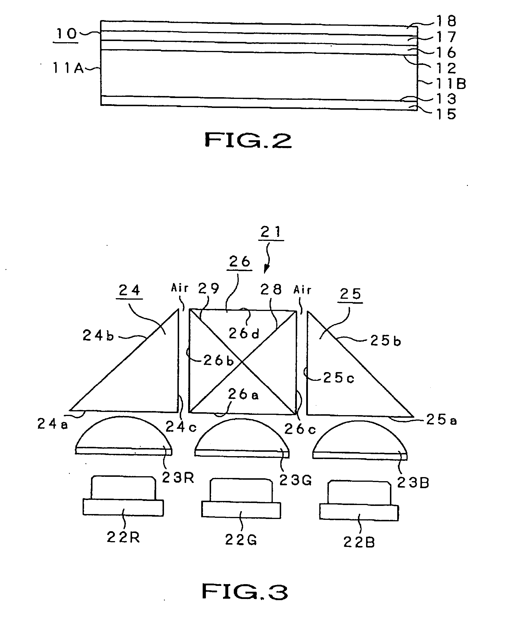
[0036] For example, in case a dichroic prism, a beam splitter prism or a beam splitter plate is used as color mixing means, and selective light transmission and reflection by a thin film formed on these optical components is carried out, it becomes possible to control the conditions for light transmission or light reflection by changing the film thickness or the material type of the thin film, which is to be formed, thus assuring facilitated adjustment for improving the color purity.

Problems solved by technology

The CCFL (Cold Cathode Fluorescent Lamp) suffers a problem that it is inferior in power consumption or useful life to the LED, or that it may have undesirable influences on global environments due to use of mercury as a gas sealed therein.
These white color emitting diodes are inferior to the CCFLs in the light emitting efficiency by approximately ⅙ pr 1 / 10, and hence are difficult to use for a liquid crystal display of the large format.
However, if such inexpensive light emitting diode is used, it is not possible with the state-of-the-art illuminating device to produce the white light of high color purity.

Method used


Image

  • Lighting system and back-light device using this lighting system
  • Lighting system and back-light device using this lighting system
  • Lighting system and back-light device using this lighting system

Examples


Embodiment Construction

[0060] An illuminating device and a backlight device according to the present invention will now be explained in detail with reference to the drawings.

[0061] Initially, a backlight unit, that goes to make up the backlight device, embodying the present invention, will be explained.

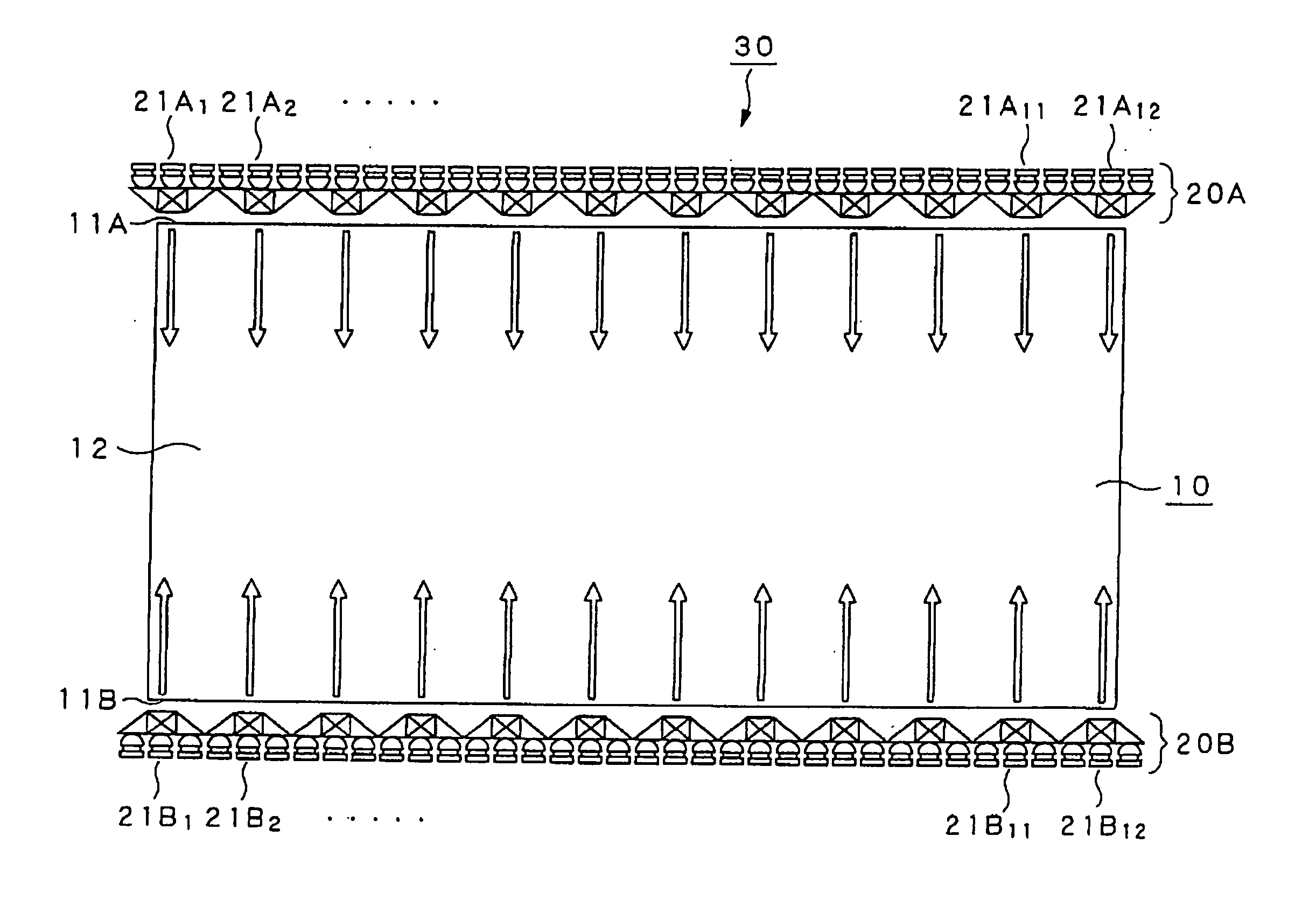
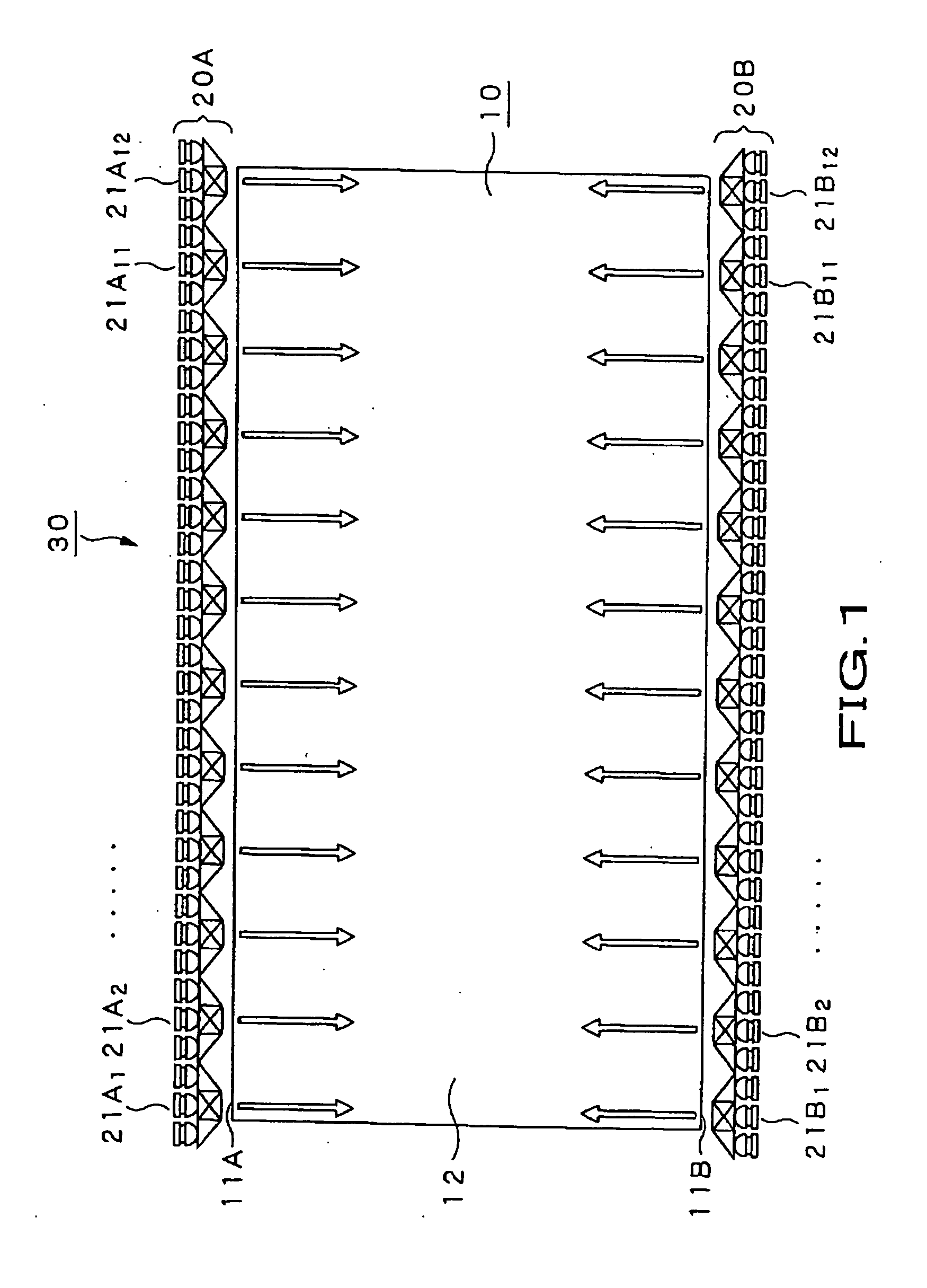
[0062] Referring to FIG. 1, a backlight unit 30 includes at least a light guide plate 10, a light source unit 20A and a light source unit 20B. The backlight unit 30 forms a backlight device illuminating a light transmitting liquid crystal display panel of a large picture image format, such as a 17-inch size light transmitting liquid crystal display panel.

[0063] A light guide plate 10, shown in FIG. 1, is a transparent plate, having an aspect ratio of, for example, 9:16, and a predetermined thickness along the direction perpendicular to the plane of the drawing sheet. The size of the light guide plate 10 also is of, for example, a 17-inch size, in keeping with the 17-inch size liquid crystal display panel...


PUM


Abstract

Disclosed is an illuminating device which, as a light source for a backlight device, mixes the colors of light rays of three prime colors radiated by light emitting diodes to emit white light. The illuminating device includes a first light source (22R) radiating light rays of the first prime color, a second light source (22G) radiating light rays of the second prime color, a third light source (22B) radiating light rays of the third prime color, optical units (23R), (23G) and (23B) which refract divergent light rays contained in the light rays of the first prime color, emitted by the first light source (22R), the light rays of the second prime color, emitted by the second light source (22G) and in the light rays of the third prime color, emitted by the third light source (22B), to form collimated light rays, and triangular prisms (24) and (25) or a dichroic prism (26) mixing the light rays of the first, second and third prime colors, emitted by these optical units, by selective transmission and reflection, based on optical properties of the light rays of the respective prime colors.

Description

TECHNICAL FIELD [0001] This invention relates to a backlight device for a liquid crystal display (LCD). More particularly, this invention relates to an illuminating device, used as a light source for a backlight device, and the backlight device employing this illuminating device. [0002] The present invention contains subject matter related to Japanese Patent Application JP 2003417337 filed in the Japanese Patent Office on Dec. 15, 2003, the entire contents of which being incorporated herein by reference. BACKGROUND ART [0003] A backlight unit, forming a backlight device of a liquid crystal display, is mainly composed of light sources and a light guide plate for guiding light rays emitted from the light sources to radiate the light rays with in-plane light radiation. The light rays emitted by the light sources are guided from a lateral surface into the bulk of the light guide plate and emitted from one of the major surfaces of the light guide plate by in-plane light radiation to illu...

Claims


Application Information

Patent Timeline
IPC IPC(8): F21V9/00F21V5/02F21V7/00G02F1/1335F21V7/22F21V8/00F21Y101/02G02F1/13357G09F13/04H01L33/58
CPCG02B6/0028G02B6/003Y10S362/80G09F13/04G02B6/0068G02F1/133G02B6/0001
Inventor HATANAKA, MASATOARAI, TAKEO
Owner SONY CORP
Learn More