Overflow Downdraw Glass Forming Method and Apparatus

a technology of glass forming and overflow, applied in glass rolling apparatus, glass tempering apparatus, instruments, etc., can solve the problems of limited apparatus, slow recovery from transient conditions, and subject to lower quality, so as to minimize air leakage in the apparatus

Inactive Publication Date: 2007-03-29
CORNING INC
View PDF36 Cites 65 Cited by
  • Summary
  • Abstract
  • Description
  • Claims
  • Application Information

AI Technical Summary

Benefits of technology

[0015] In a preferred embodiment of the present invention, all the glass that forms the surface of the useful area of the sheet is virgin glass, which is not contaminated by flow in proximity to a refractory or refractory metal surface after the stirring operation. In addition, this embodiment significantly reduces inhomogeneities in the glass that forms the sheet by eliminating the regions of quiescent flow in the piping between the stirring device and the sheet glass forming apparatus.
[0016] In another preferred embodiment, this invention introduces a precise thermal control system to redistribute the flow of molten glass at the weirs which is the most critical area of the forming process. This thermal control effectively counteracts the degradation of the sheet forming apparatus which inevitably occurs during a production campaign.
[0018] Another preferred embodiment creates a variable external cross-section which alters the direction and magnitude of the surface tension and body force stresses and thus, reduces the adverse influence of surface tension and body forces on sheet width.
[0020] In a further preferred embodiment, this invention adjusts the internal pressure in each of the major components of the forming apparatus such that the pressure difference across any leakage path to the forming zone approaches zero. Therefore, air leakage in the apparatus is minimized even though cracks and openings exist during initial operation and develop during manufacturing.
[0021] In yet another preferred embodiment, the invention introduces a counteracting force to the stresses caused by gravitational forces on the forming structure in a manner such that the thermal creep deformation (strain) that results from thermal creep has a minimum effect on the thickness variation of the glass sheet.

Problems solved by technology

However, the apparatus has limitations.
A major drawback of the apparatus of “The Overflow Process” is that, even though it makes excellent glass over most of the surface, the surface of the glass sheet nearest the inlet is composed of glass that has flowed in proximity to the feeding pipe surfaces and therefore is subject to lower quality.
Another drawback of the apparatus of “The Overflow Process” is that, even though its makes excellent glass during stable operating conditions, it recovers from transient conditions very slowly.
During unintended process transients, these quiescent zones slowly bleed glass of a previous material composition into the main process stream of glass causing defects.
These defects eventually subside when the process stabilizes; however, there is a period of time where the quality of the glass sheet is substandard.
Yet another drawback of the apparatus of “The Overflow Process” is the limited means for controlling the thickness of the formed sheet.
This lack of control can have a significant impact on the flatness (warp) of the formed sheet.
A further drawback of the apparatus of “The Overflow Process” is that surface tension and body forces have a major effect on the molten glass flow down the external sides of the forming apparatus causing the sheet to be narrower than the forming apparatus and the edges of the formed sheet to have thick beads.
Yet another drawback of the apparatus of “The Overflow Process” is that the drawing of the sheet from the bottom of the apparatus has a propensity to have a cyclic variation in sheet thickness.
As the apparatus ages, air leaks develop through cracks in material and assorted openings caused by differential expansion.
A significant drawback of the apparatus of “The Overflow Process” is that the forming apparatus deforms during a manufacturing campaign in a manner such that the glass sheet no longer meets the thickness specification.
This is a primary cause for premature termination of the production run.
This adjustment activity leads to loss of salable product.

Method used


Image

  • Overflow Downdraw Glass Forming Method and Apparatus
  • Overflow Downdraw Glass Forming Method and Apparatus
  • Overflow Downdraw Glass Forming Method and Apparatus

Examples


Embodiment Construction

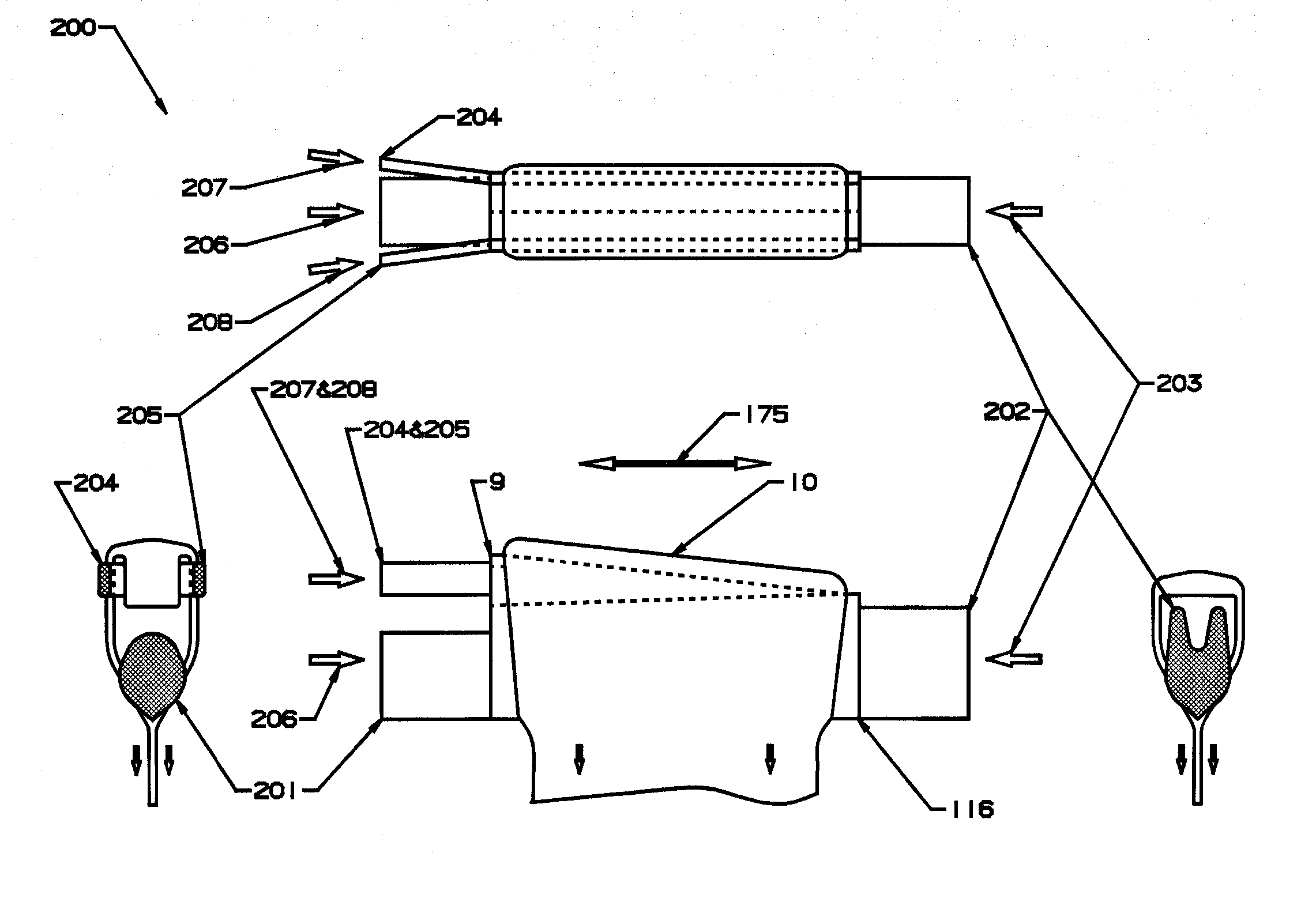
[0171] The flow dynamics in all embodiments of this invention are such that the outside surfaces of the glass sheet are formed from thoroughly mixed virgin glass that comes from the center of the glass stream flowing into the forming apparatus and thus has not contacted a refractory or refractory metal surface. This produces the highest possible surface quality. This pristine surface is essential for the manufacture of LCD / TFT semiconductor display devices. In addition, the flow dynamics in all embodiments of this invention are such that the flow rate of molten glass to the forming wedge at the bottom of the forming structure is substantially uniform over its width.

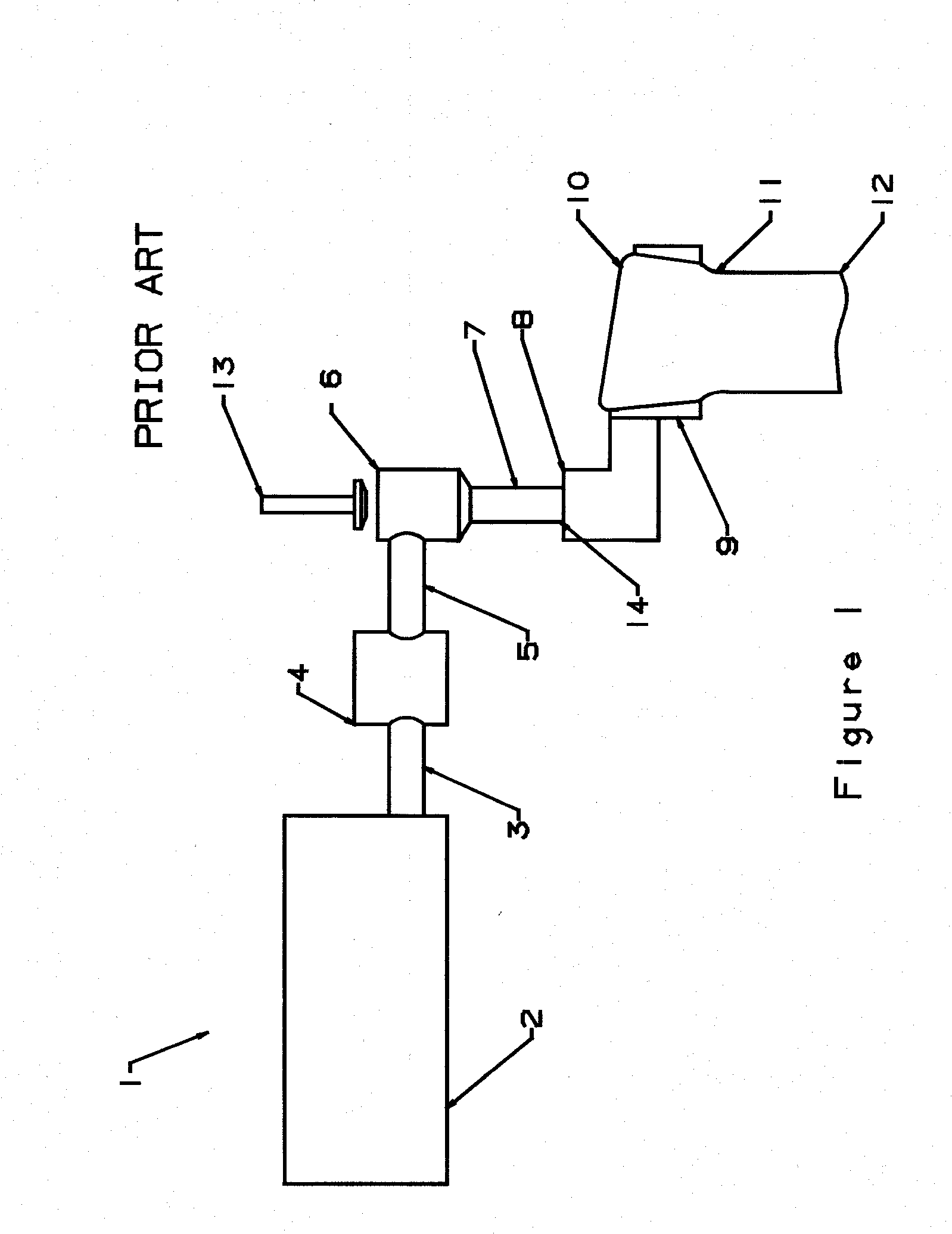
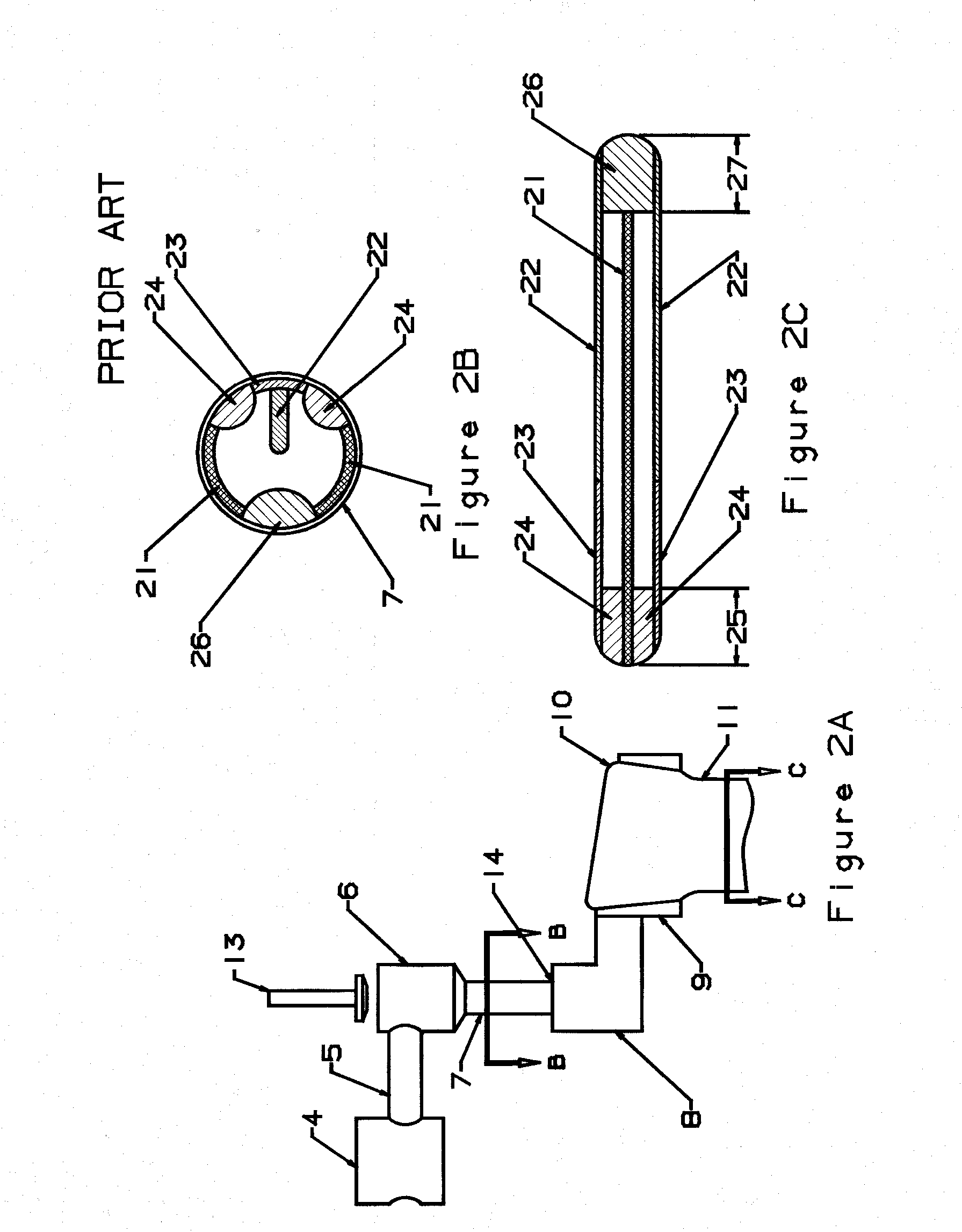
[0172] The glass “Sheet Forming Apparatus” normally designed for use in “The Overflow Process” (U.S. Pat. No. 3,338,696) relies on a specifically shaped forming structure to distribute the glass in a manner to form a sheet of a uniform thickness. The basic shape of this forming structure is described in detail in U.S. Pa...


PUM

PropertyMeasurementUnit
included half angleaaaaaaaaaa
distancesaaaaaaaaaa

Abstract

The present invention discloses improved methods and apparatus for forming sheet glass. In one embodiment, the invention introduces a counteracting force to the stresses on the forming structure in a manner such that the thermal creep which inevitably occurs has a minimum impact on the glass flow characteristics of the forming structure.

Description

BACKGROUND OF THE INVENTION [0001] 1. Field of the Invention [0002] This invention relates generally to the manufacture of glass sheet and, more particularly, to glass sheet used for the production of LCD display devices that are widely used for computer displays. [0003] 2. Description of Related Art [0004] The glass that is used for semiconductor powered display applications, and particularly for TFT / LCD display devices that are widely used for computer displays, must have very high surface quality to allow the successful application of semiconductor type material. Sheet glass made using the apparatus of U.S. Pat. No. 3,338,696, assigned to Corning, Inc., makes the highest quality glass as formed and does not require post-processing. The Corning patent makes glass by a manufacturing process termed: “The Overflow Process”. Glass made using other processes requires grinding and / or polishing and thus does not have as fine a surface finish. The glass sheet must also conform to stringen...

Claims


Application Information

Patent Timeline
Patent Type & Authority Applications(United States)
IPC IPC(8): C03B13/00C03B5/26
CPCC03B17/067C03B17/064Y02P40/57
Inventor PITBLADDO, RICHARD B.
Owner CORNING INC
Why Eureka
Try Eureka