Fuel injection strategy for reduced cold start emission from direct injection gasoline engines

Active Publication Date: 2007-03-29
FORD GLOBAL TECH LLC
View PDF18 Cites 49 Cited by
  • Summary
  • Abstract
  • Description
  • Claims
  • Application Information

AI Technical Summary

Benefits of technology

[0005] In this way, it may be possible to achieve improved vaporization via the first injection at least partially during the exhaust stroke. Further, it may be possible to achieve this vaporization while reducing piston wetting by using at least a second injection event during engine cold starting. In oth

Problems solved by technology

The inventors herein have recognized a disadvantage with such an approach.
Specifically, a single injection o

Method used


Image

  • Fuel injection strategy for reduced cold start emission from direct injection gasoline engines
  • Fuel injection strategy for reduced cold start emission from direct injection gasoline engines
  • Fuel injection strategy for reduced cold start emission from direct injection gasoline engines

Examples


Embodiment Construction

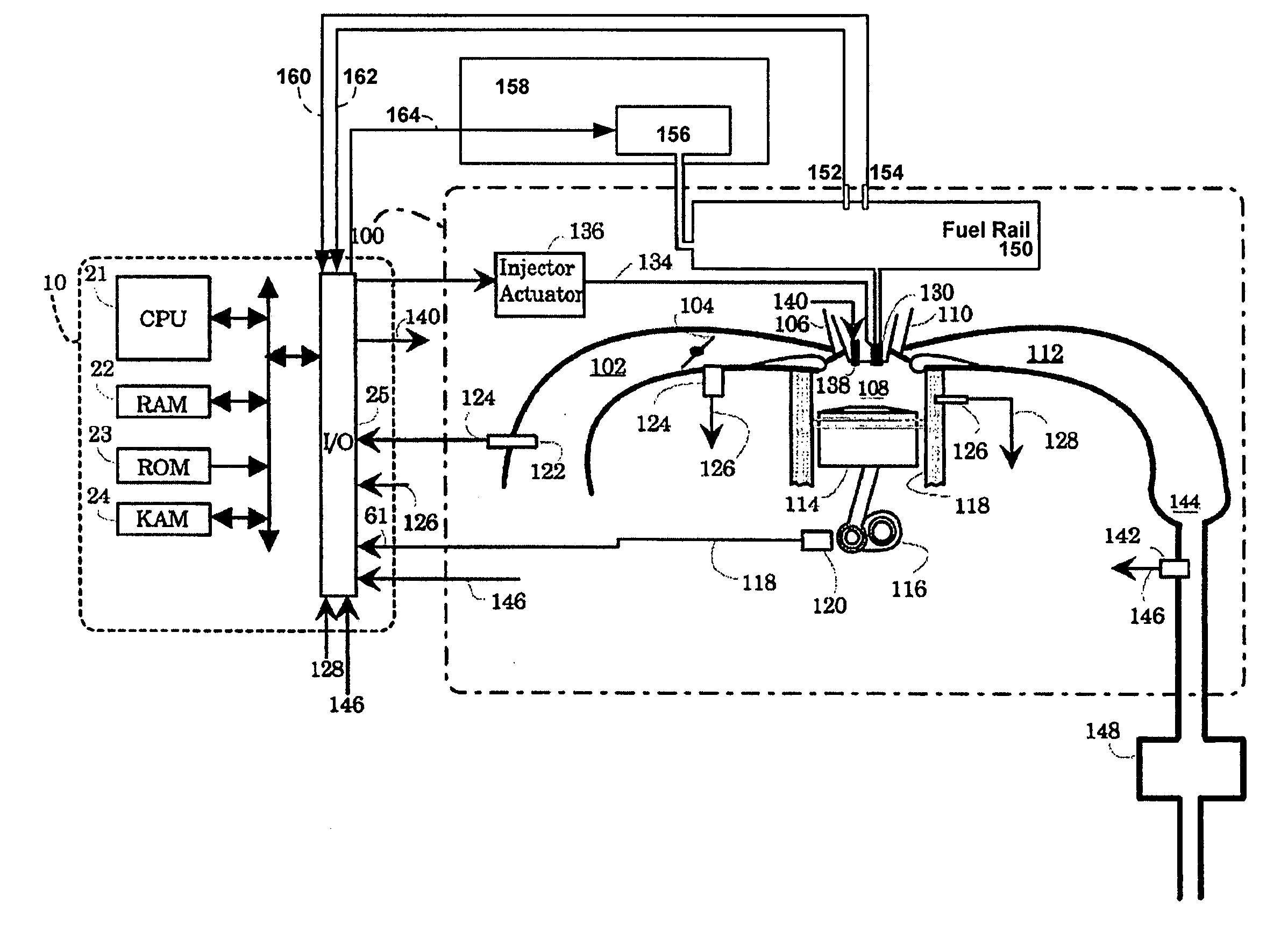
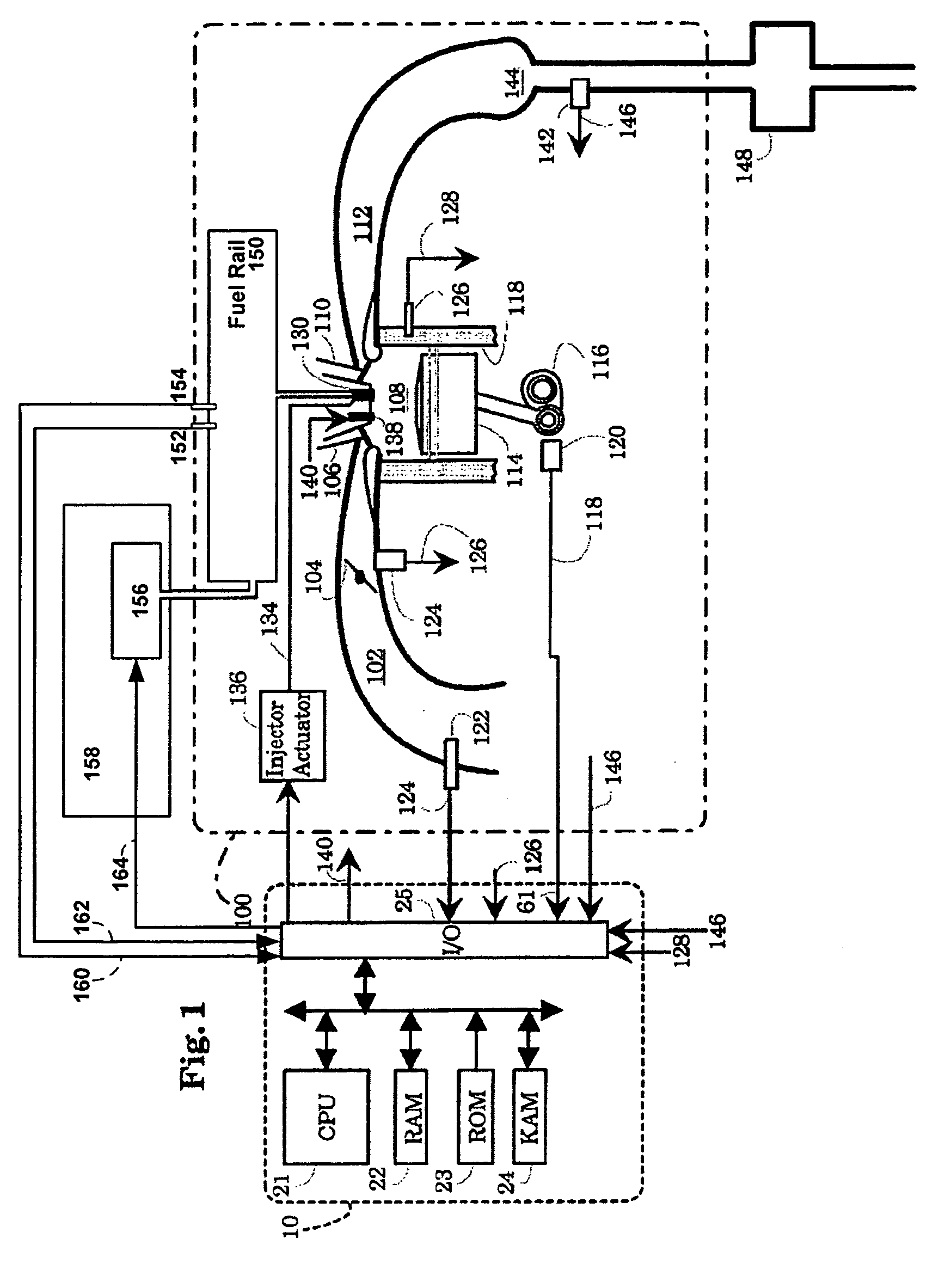
[0012]FIG. 1 of the drawings shows an Electronic Engine Controller (EEC) 10 and an internal combustion engine 100, which comprises a plurality of cylinders, one of which is shown in FIG. 1. Engine 100 draws an aircharge through an intake manifold 102, past a throttle plate 104, and intake valve 106 and into combustion chamber 108. An air / fuel mixture which includes air supplied by the intake valve and / or exhaust valve and fuel injected by fuel injector 130 is ignited in combustion chamber 108, and exhaust gas produced from combustion of the air / fuel mixture is transported past exhaust valve 110 through exhaust manifold 112. A piston 114 is coupled to a crankshaft 116, and moves in a linear fashion within a cylinder defined by cylinder walls 118.

[0013] A crankshaft position sensor 120 detects the rotation of crankshaft 116 and transmits a crankshaft position signal 118 to EEC 10. Crankshaft position signal 118 may take the form of a series of pulses, each pulse being caused by the r...


PUM


Abstract

A system, comprising of an engine having a cylinder therein, a fuel injector coupled to said cylinder and configured to directly inject fuel into said cylinder, a fuel system coupled to said injector, and a controller configured to control engine starting operation, wherein during a start, said fuel injector performs a first fuel injection at least partially during an exhaust stroke of said cylinder, where fuel from said first fuel injection is mixed with air inducted at least during an intake stroke following said exhaust stroke, said fuel injector performing a second fuel injection after said first fuel injection, and combusting fuel from said first and second fuel injections to perform a combustion event in said cylinder.

Description

BACKGROUND AND SUMMARY [0001] Strategies have been developed in order to reduce the tailpipe hydrocarbon emissions produced during vehicle startup while simultaneously obtaining reliable combustion and increasing exhaust heat for catalyst heating. In one example, intake port fuel injection can be used to provide a selected air-fuel ratio for combustion. In another example, direct fuel injection may be used to improve control over fuel delivery during a cold start. [0002] One approach to facilitating fuel injection control in a direct injection engine during startup is described in U.S. Pat. No. 5,794,586. In this approach, a fuel injection control system provides a means of delivering fuel in a single low pressure injection during startup. In particular, the approach relies on a single injection of fuel initiated late in the exhaust stroke that persists throughout the intake stroke in order to facilitate the vaporization of the fuel during cold start applications. In this manner, th...

Claims


Application Information

Patent Timeline
IPC IPC(8): F02B3/00F02M1/00F02M51/00F02D41/06F02N17/00F02N99/00
CPCF02D41/009F02D41/0255F02D41/062F02D41/064F02D41/086F02D41/402Y02T10/26F02D2041/389F02D2200/703F02M45/02F02M69/00Y02T10/44F02D41/403Y02T10/12Y02T10/40
Inventor HILDITCH, JAMES
Owner FORD GLOBAL TECH LLC
Why Eureka
Try Eureka