Rotor for an electrical motor

a technology of rotor and electrical motor, which is applied in the direction of asynchronous induction motors, electric devices, dynamo-electric machines, etc., can solve the problems of overall increase of efficiency, reducing electrical efficiency, and gaps, and achieve the effect of improving the efficiency of electrical motor

Inactive Publication Date: 2007-03-29
DANFOSS COMPRESSORS
View PDF18 Cites 11 Cited by
  • Summary
  • Abstract
  • Description
  • Claims
  • Application Information

AI Technical Summary

Benefits of technology

[0005] It is one object of the present invention to improve the efficiency of an electrical motor. Accordingly, the present invention, in a first aspect, provides a rotor for an electrical motor of the kind mentioned in the introduction and characterized in that a first of either the outer peripheral surface or the inner peripheral surface adapted to be closest to the stator of an associated electrical motor comprises a curved portion which slopes in a direction towards the other second surface.
[0006] Normally, the induction of the voltage in the short circuit ring causes a watt loss producing electrical circulation current in the short circuit ring, and due to the curved portion, the eddy-current braking effect can be reduced. As a result, the efficiency of the motor is improved. Although the electrical conductivity of the curved short circuit ring is reduced by the inventive measure compared to a conventional short circuit ring, thus reducing the electrical efficiency, the gain in reducing the circulation currents caused by the stray field results in an overall increase of the efficiency. Thus, when designing the curvature of the curved portion, attention must be given to minimise the reduction in electrical conductivity of the short circuit ring. Further, besides the electrical resistance of the ring, the shape of the curved portion is a function of the desired flow during moulding of the short circuit ring. If the curved portion has an incorrect curving the aluminium will not flow into the corners, thus leaving gaps.

Problems solved by technology

Although the electrical conductivity of the curved short circuit ring is reduced by the inventive measure compared to a conventional short circuit ring, thus reducing the electrical efficiency, the gain in reducing the circulation currents caused by the stray field results in an overall increase of the efficiency.
If the curved portion has an incorrect curving the aluminium will not flow into the corners, thus leaving gaps.

Method used


Image

  • Rotor for an electrical motor
  • Rotor for an electrical motor
  • Rotor for an electrical motor

Examples


Embodiment Construction

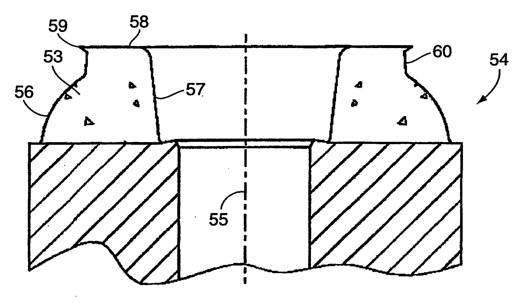
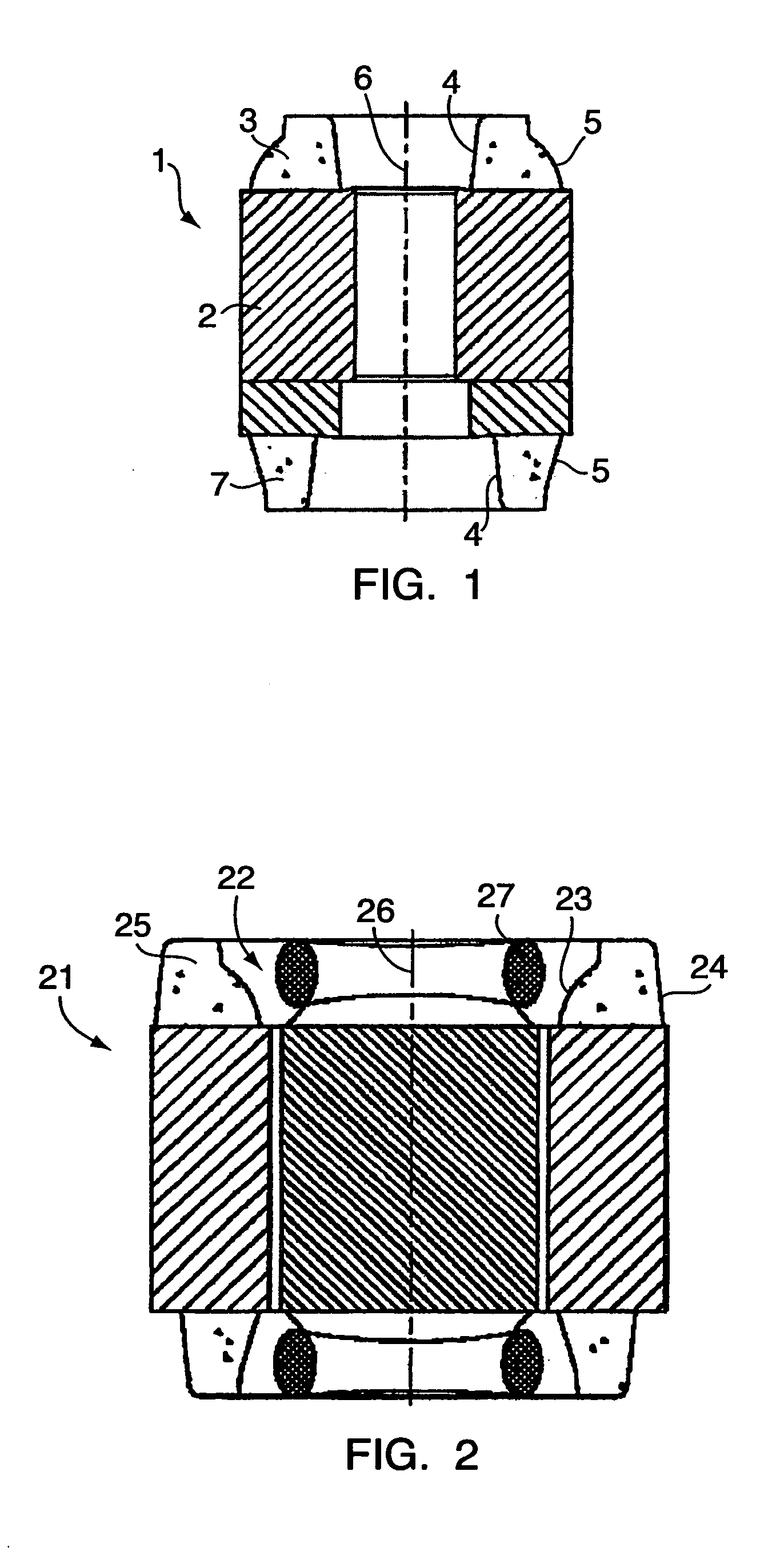
[0028]FIG. 1 shows a squirrel cage rotor 1 having a plurality of conductors fastened to or moulded into channels of a rotor core 2 and connected in each of the axially disposed ends to a short circuit ring 3, 7. The short circuit ring is annular with an inner peripheral surface 4 and an outer peripheral surface 5. The rotor can be arranged either internally inside or externally outside a tubular stator (not shown in FIG. 1) so that one of either the internal surface 4 or the external surface 5 becomes the one of the surfaces of the annular body being closest to the stator. In FIG. 1, the external surface 5 is adapted to be closest to a stator. The external surface is curved to increase the efficiency of the motor. The angle of a tangent to the curved surface has a numerical value which is larger than the corresponding angle of the internal surface 4 to the centre axis 6. In a cross sectional view, the internal and external surfaces are bevelled linearly towards each other. FIG. 4, h...


PUM


Abstract

The present invention provides to a rotor having a short circuit ring of an electrically conductive material. The short circuit ring has a curved outer surface whereby the eddy-current braking effect on the rotor caused by the stray field from the stator is reduced. The curved surface leads to an improved efficiency of an associated electrical motor. The invention further provides a motor with such a rotor and to the use of a rotor in an electrical motor.

Description

CROSS REFERENCE TO RELATED APPLICATIONS [0001] This application is entitled to the benefit of and incorporates by reference essential subject matter disclosed in International Patent Application No. PCT / DK2004 / 000306 filed on May 5, 2004 and Danish Patent Application No. PA 2003 00674 filed May 6, 2003.FIELD OF THE INVENTION [0002] The present invention relates to a rotor for an electrical induction motor of the kind provided with a rotor having windings connected to a short circuit ring. In particular, the invention relates to a rotor for an electrical motor of the kind provided with a stator and a winding generating a stray field that induces a voltage into a short circuit ring of the rotor, the short circuit ring forming an end part of the rotor, said end part having the shape of an annular body with an outer peripheral surface and an inner peripheral surface coaxially extending around a centre axis. The invention further relates to an electrical motor comprising the rotor, and t...

Claims


Application Information

Patent Timeline
Patent Type & Authority Applications(United States)
IPC IPC(8): H02K17/00H02K19/14H02K17/16
CPCH02K17/165
Inventor WEIHRAUCH, NIELS CHRISTIAN
Owner DANFOSS COMPRESSORS
Why Eureka
Try Eureka