
Optical heterodyne receiver and method of extracting data from a phase-modulated input optical signal

a phase-modulated input and optical signal technology, applied in the field of optical receivers, can solve the problems of limiting low carrier frequency, and low signal bandwidth, and achieve the effect of reducing the dynamic range of phase tracking, and reducing the frequency of phase tracking

Inactive Publication Date: 2007-03-29
ALCATEL-LUCENT USA INC +1
View PDF9 Cites 42 Cited by
  • Summary
  • Abstract
  • Description
  • Claims
  • Application Information

AI Technical Summary

Benefits of technology

The present invention provides an optical heterodyne receiver that can extract data from a phase-modulated input optical signal. The receiver includes a photonic quadrature demodulator, a passive radio-frequency single-sideband demodulator, and a base band processor with sigma-delta analog-to-digital converters. The receiver can execute a Model-Based Phase Demodulation (MBPD) process with respect to the sidebands generated by the demodulators. The technical effects of the invention include improved accuracy and efficiency in extracting data from optical signals and improved performance of optical communication systems.

Problems solved by technology

Unfortunately, phase discriminators exhibit nonlinearities, which limit their dynamic range.
Unfortunately, phase tracking works well for rather small signal bandwidths and low carrier frequencies.
Unfortunately, this non-linear process exhibits intermodulation distortion (IMD) at high carrier frequencies.
Therefore, the WIRNA architecture cannot be used for a receiver required to operate with respect to a wide range of center carrier frequencies.
Unfortunately, the bandwidth that is required of the receiver becomes immense.
Traditional phase demodulation techniques become essentially unworkable.

Method used


Image

  • Optical heterodyne receiver and method of extracting data from a phase-modulated input optical signal
  • Optical heterodyne receiver and method of extracting data from a phase-modulated input optical signal
  • Optical heterodyne receiver and method of extracting data from a phase-modulated input optical signal

Examples


Embodiment Construction

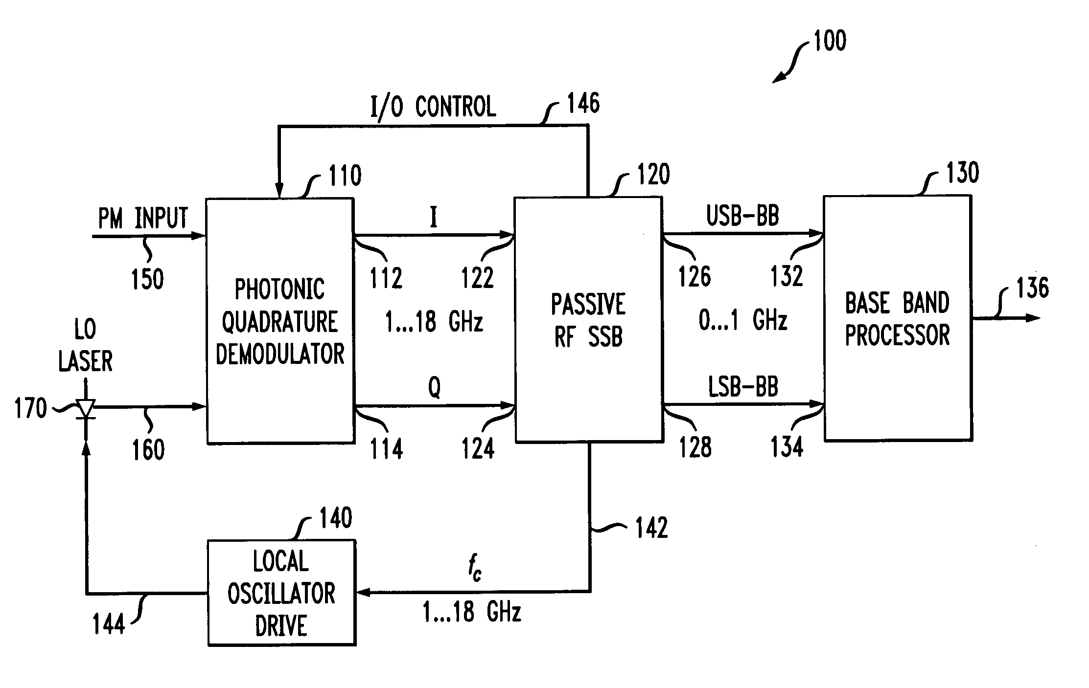
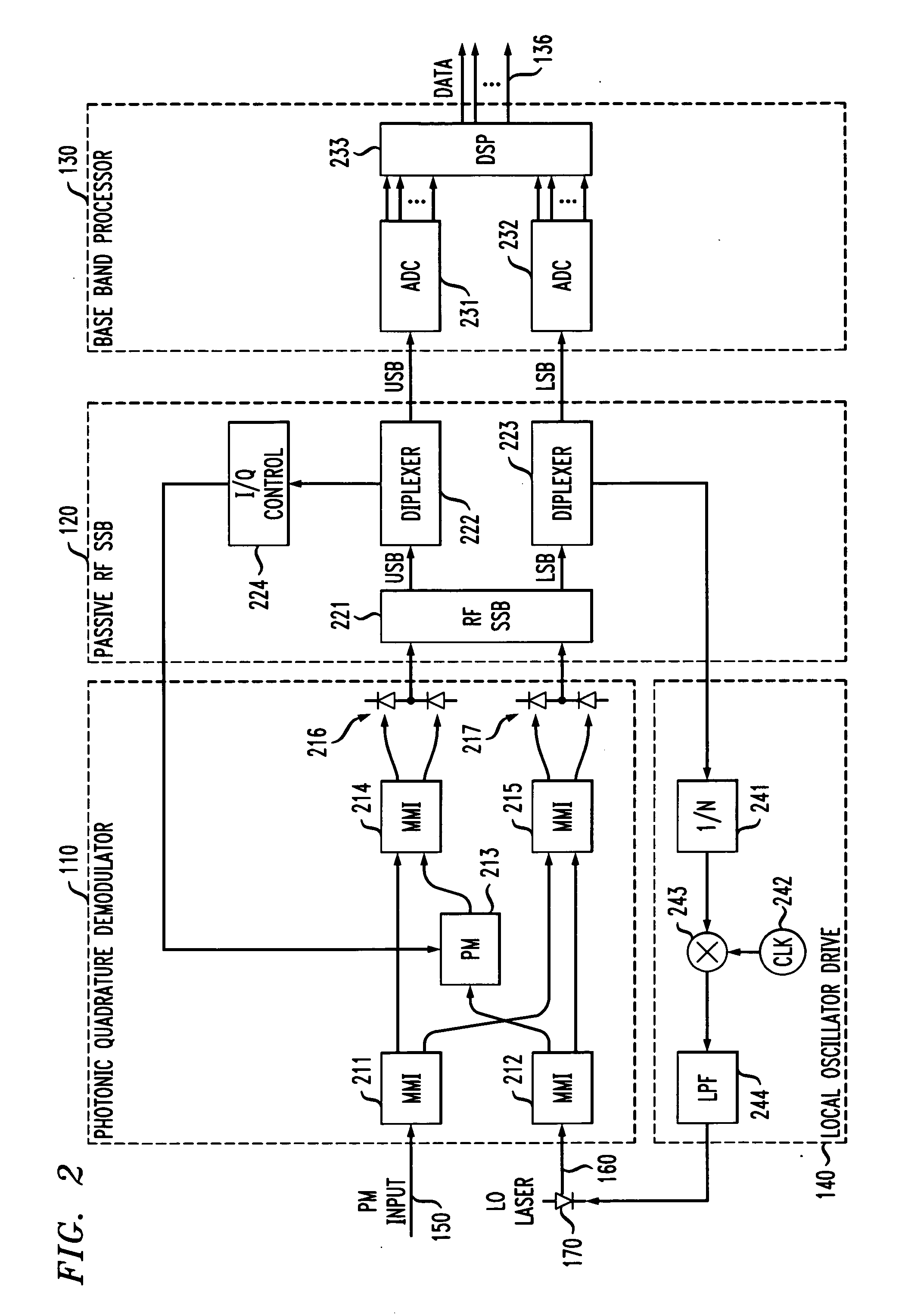
[0019] The optical heterodyne receiver 100 introduces novel features to circumvent the limitations in the aforementioned traditional approaches. First, the optical heterodyne receiver 100 uses a fixed, low, intermediate frequency (IF) frequency band for signal detection. In particular, a coherent heterodyne receiver is used with the local oscillator laser offset by the microwave carrier frequency to align the first side-lobe of the phase modulated optical signal to the local oscillator laser within a predefined IF frequency band, e.g., around 500 MHz. In the illustrated embodiment, only this frequency band is used for data recovery. Second, the optical heterodyne receiver 100 implements a novel signal-processing-based approach to demodulate the transmitted signal in which the signal bandwidth falls within the bandwidth of base band analog-to-digital converters (ADCs) or passband of sigma-delta ADCs. Only the nonlinearity of the photodetector limits the IMD, because of the near-ideal...


PUM


Abstract

An optical heterodyne receiver and a method of extracting data from a phase-modulated input optical signal. In one embodiment, the optical heterodyne receiver includes: (1) a photonic quadrature demodulator having first and second optical inputs and first and second electrical outputs and configured to generate at the first and second electrical outputs an in-phase signal and a quadrature-phase signal, respectively, in response to receiving a modulated optical signal at the first optical input and a reference optical oscillator signal at the second optical input, (2) a passive radio frequency single sideband demodulator coupled to the photonic quadrature demodulator and configured to extract at least one sideband of the in-phase signal or the quadrature-phase signal and (3) at least one analog-to-digital converter coupled to the passive radio frequency single sideband demodulator and configured to receive and sample the at least one sideband.

Description

TECHNICAL FIELD OF THE INVENTION [0001] The present invention is directed, in general, to optical receivers and, more specifically, to an optical heterodyne receiver and a method of extracting data from a phase-modulated input optical signal. BACKGROUND OF THE INVENTION [0002] Optical transmission systems, which use coherent (laser) light and optical fibers to send data, often employ phase modulation to encode data in an optical carrier wave. [0003] The phase-modulated light must eventually be received and demodulated by an optical receiver to yield electrical signals. It is vital that the receiver be capable of receiving, demodulating and decoding the data contained in the optical signal as quickly as it is received. [0004] Some traditional phase demodulation techniques rely on a phase discriminator (typically a simple delay-line filter), an envelope detector and an integrator. Unfortunately, phase discriminators exhibit nonlinearities, which limit their dynamic range. Other phase ...

Claims


Application Information

Patent Timeline
Patent Type & Authority Applications(United States)
IPC IPC(8): H04B10/06
CPCH04B10/61H04B10/64H04B10/615H04B10/613
Inventor CHEN, YOUNG-KAIKOC, UT-VALEVEN, ANDREAS
Owner ALCATEL-LUCENT USA INC
Learn More