Method and apparatus for wafer-level micro-glass-blowing

a micro-glass-blowing and wafer-level technology, applied in glass reforming apparatus, glass tempering apparatus, turn-sensitive devices, etc., can solve the problems of inability to achieve a spherical shape with traditional etching techniques, inability to use conventional glass-blowing to create large components,

Active Publication Date: 2007-03-29
RGT UNIV OF CALIFORNIA
View PDF3 Cites 30 Cited by
  • Summary
  • Abstract
  • Description
  • Claims
  • Application Information

AI Technical Summary

Benefits of technology

[0013] The method of the illustrated embodiment allows for microfabrication compatible micro-glass-spheres, integrated on a substrate, wafer or chip. These spheres can be filled by gases or other substances post fabrication. In the illustrated embodiment of the invention, the spheres are attached to a wafer, allowing for integration with conventional micro-fabrication components and allowing for batch-fabrication of micro-glass components.
[0014] The invention includes a method for shaping glass on a microscopic scale to mass-produce multiple glass components, i.e. shaped simultaneously on a micro-scale. This is accomplished by bonding a thin sheet of glass to a perforated wafer, heating the glass, and then blowing the glass from the reverse side of the wafer. One potential application of this invention is as a confinement chamber for various gases. The chambers are much smaller than traditional glass-blown chambers and are micro-fabrication compatible.
[0024] In the illustrated embodiment the resistive heater is made from a material that has a high melting temperature, and the method further comprises the step of protecting portions of the thermally formable material using the resistive heater as the heat-shield to reduce the risk of undesired deformation of selected areas of the thermally formable material when heated above its softening point.

Problems solved by technology

However, all of these prior efforts have dealt with the fabrication of spheres that are not attached to any surface and can only be filled with specific gases during the fabrication process.
However, etching usually leads to rough surfaces as well as very thick sidewalls making it unfit for many applications (e.g. when optics need to be integrated with the chamber).
Furthermore, it is not possible to achieve a spherical shape with traditional etching techniques.
However, conventional glass-blowing can only be used to create large components (not micro-fabrication compatible).

Method used


Image

  • Method and apparatus for wafer-level micro-glass-blowing
  • Method and apparatus for wafer-level micro-glass-blowing
  • Method and apparatus for wafer-level micro-glass-blowing

Examples


Embodiment Construction

[0039] The illustrated embodiments of the invention was developed as a microscopic gas confinement chamber, but many other applications are expressly considered as within the scope of the invention, e.g. vapor cells for nuclear magnetic resonance gyroscopes, micro-lamps, and hydrogen capsules for H-vehicles. Other applications include laser fusion targets, as well as lab-on-a-chip, medication capsules, and other biomedical devices. This listing by no means exhausts the list of potential uses and applications of the invention.

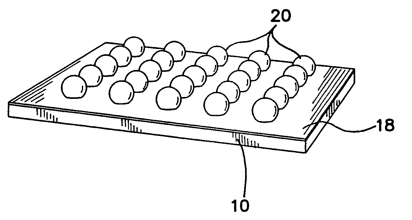
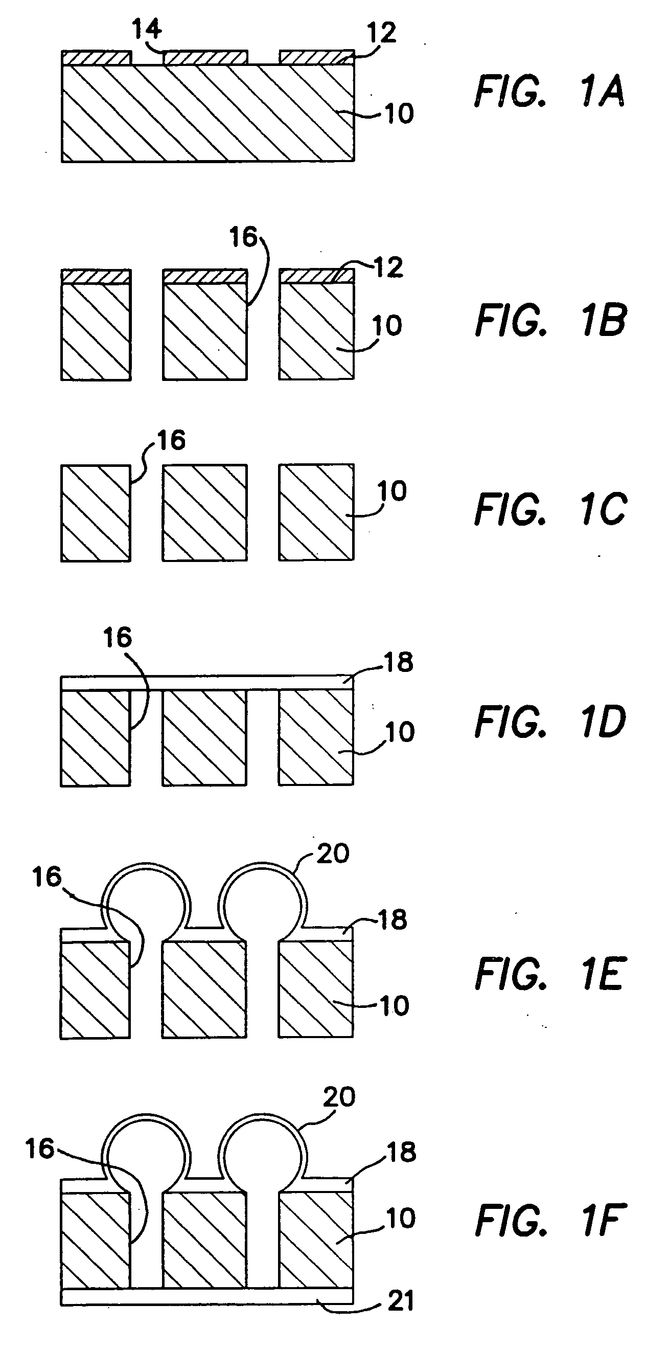
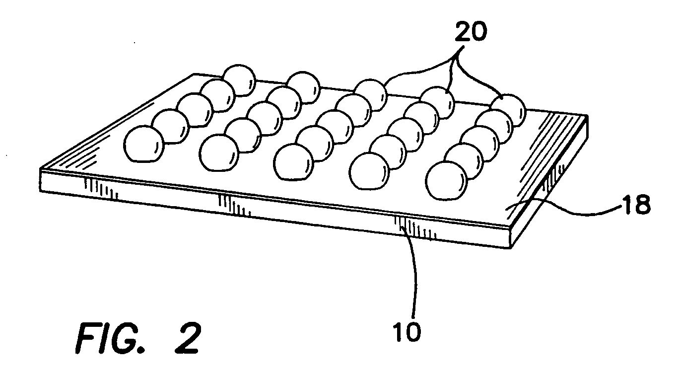
[0040]FIGS. 1a-1f depict the illustrated embodiment fabrication process. In FIG. 1a a photoresist layer 12 is disposed on a substrate 10 and patterned to define a plurality of openings 14 defined in photoresist layer 12. Cylindrical holes 16 are then etched in FIG. 1b all the way through a silicon substrate 10, preferably using deep-reactive ion etching (DRIE). The photoresist layer 12 is removed from the top of the perforated substrate 10 as shown in FIG. 1c. ...


PUM

PropertyMeasurementUnit
thickaaaaaaaaaa
thickaaaaaaaaaa
degree of plasticityaaaaaaaaaa

Abstract

A method for forming microspheres on a microscopic level comprises the steps of defining holes through a substrate, disposing a sheet of thermally formable material onto the substrate covering the holes, heating the sheet of thermally formable material until a predetermined degree of plasticity is achieved, applying fluidic pressure through the holes to the sheet of thermally formable material, while the sheet of glass is still plastic, and forming microspheres on the substrate in the sheet of thermally formable material by means of continued application of pressure for a predetermined time. The invention also includes a substrate having a plurality of holes defined therethrough, a layer of thermally formable material disposed onto the substrate covering the plurality of holes, and a plurality of microspheres thermally formed in the layer by means of applied pressure through the holes when it has been heated to a predetermined degree of plasticity.

Description

RELATED APPLICATIONS [0001] The present application is related to U.S. Provisional Patent Application, Ser. No. 60 / 721,172, filed Sep. 27, 2005, which is incorporated herein by reference and to which priority is claimed pursuant to 35 USC 119.BACKGROUND OF THE INVENTION [0002] 1. Field of the Invention [0003] The invention relates to the field of micromachined glass components and methods of manufacture of the same. [0004] 2. Description of the Prior Art [0005] In addition to consumer glass products, glass-blowing is often used to create confinement chambers for different types of gases. A normal glass-blowing process is (roughly) as follows: [0006] Heat the glass to its softening point [0007] Remove glass from the heat source (e.g. flame) [0008] Immediately apply pressure (blowing) to shape the glass [0009] Repeat all steps if needed [0010] In the past, micro-spheres have been fabricated using polymer droplets that are allowed to fall through a high column whose temperature profile...

Claims


Application Information

Patent Timeline
Patent Type & Authority Applications(United States)
IPC IPC(8): C03C17/32C03B19/10C03B19/08
CPCC03B23/02Y10T428/1317G01C19/60B81C1/00B81B2201/058B81C1/00103
Inventor EKLUND, E. JESPERSHKEL, ANDREI M.
Owner RGT UNIV OF CALIFORNIA
Why Eureka
Try Eureka