Electric fan

a technology of electric fans and stator cores, which is applied in the direction of positive displacement liquid engines, magnetism circuit shapes/forms/construction, piston pumps, etc., can solve the problems of increasing the size of the cooling fan, difficult to alter, and the size and shape of the stator cores are pretty much fixed and difficult to change, so as to reduce the flow resistance of airflow, avoid air-flow turbulence and noise, and the effect of large siz

Inactive Publication Date: 2007-04-05
HON HAI PRECISION IND CO LTD
View PDF6 Cites 22 Cited by
  • Summary
  • Abstract
  • Description
  • Claims
  • Application Information

AI Technical Summary

Benefits of technology

[0006] According to a preferred embodiment of the present invention, an electric fan includes a frame having a central tube extending therefrom, a bearing received in the central tube, a stator mounted around the central tube, and a rotor being rotatably supported by the bearing. The frame defines an air inlet and an air outlet at two different sides thereof. The stator includes a stator core having a central cylinder. A plurality of radial posts extend from the central cylinder. A plurality of magnetic poles are formed at free ends of the posts. Each magnetic pole includes a lower portion adjacent to the air outlet and an upper portion adjacent to the air inlet; the upper portions expand radially along a direction from the air inlet to the air outlet. The rotor includes a hub and a plurality of blades extending from an outer-periphery of the hub. An upper portion of the hub expands radially along the flow direction. Thus the outer surface of the hub has a streamlined shape with the outer surface with the smallest diameter facing the air inlet of the fan; the flow resistance of the airflow is reduced and the air-flow turbulence and noise are avoided. The fan blades of the rotor have a larger size and thus can generate a larger amount of airflow. As a result a greater amount of airflow with increased speed and pressure is generated, and the heat dissipation efficiency of the electric fan is improved.

Problems solved by technology

However, this way will increase the size of the cooling fan, which is disadvantageous in view of the degree of miniaturization required in electronic products.
However, the yokes of the stator core 62 are formed by stamping silicon-steel sheets, each of which has a flat configuration and a predetermined diameter; thus, the size and the shape of the stator core 62 are pretty much fixed and difficult to alter.
Furthermore, the flat, disc-shaped top wall 81 of the hub 82 forms a barrier for the airflow through the fan, thus adversely affecting the flow rate of the airflow.
Accordingly, the airflow provided by the conventional electric fan cannot efficiently dissipate heat absorbed by a heat sink from a heat-generating electronic component away from the heat sink.

Method used


Image

  • Electric fan
  • Electric fan
  • Electric fan

Examples


Embodiment Construction

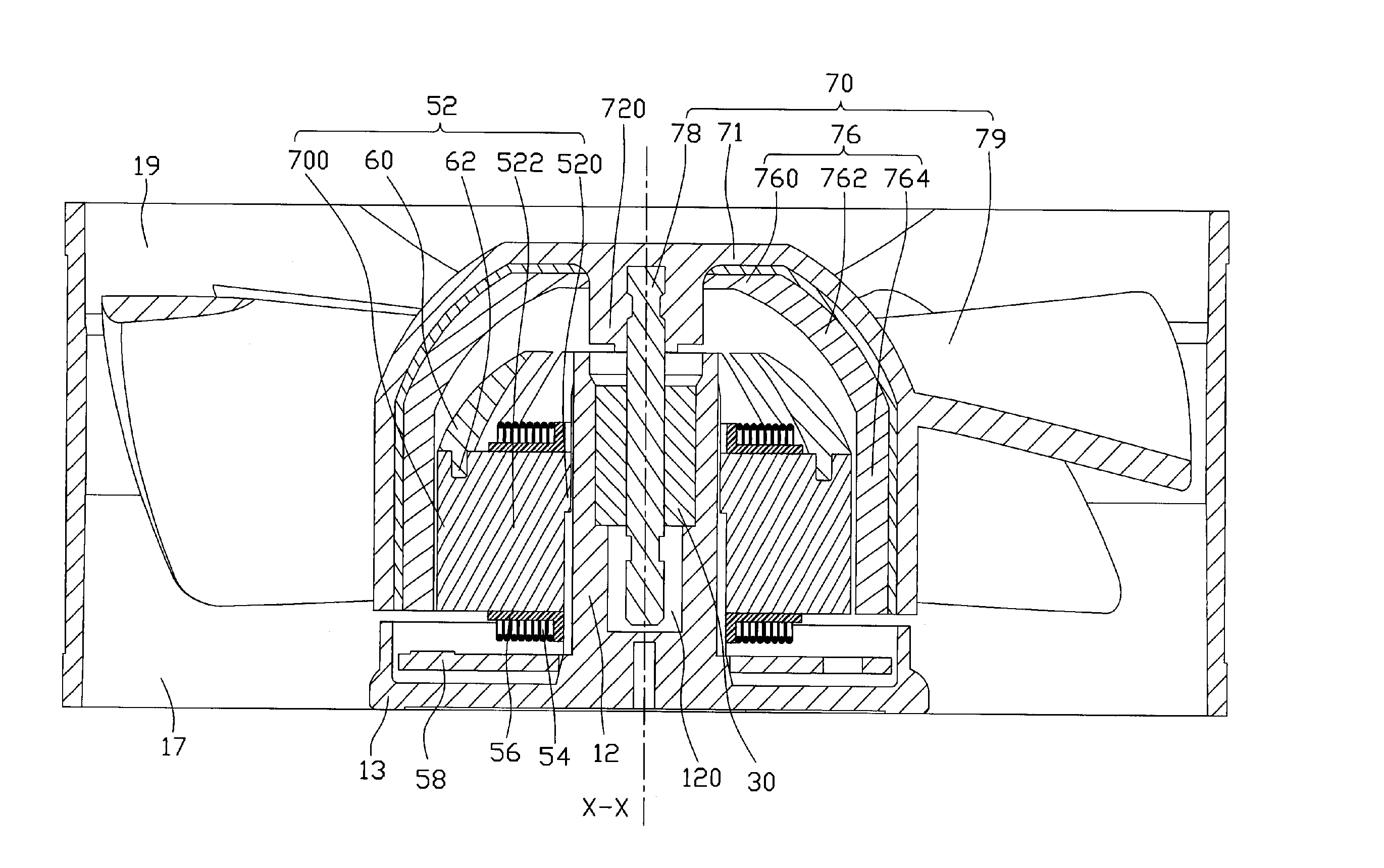
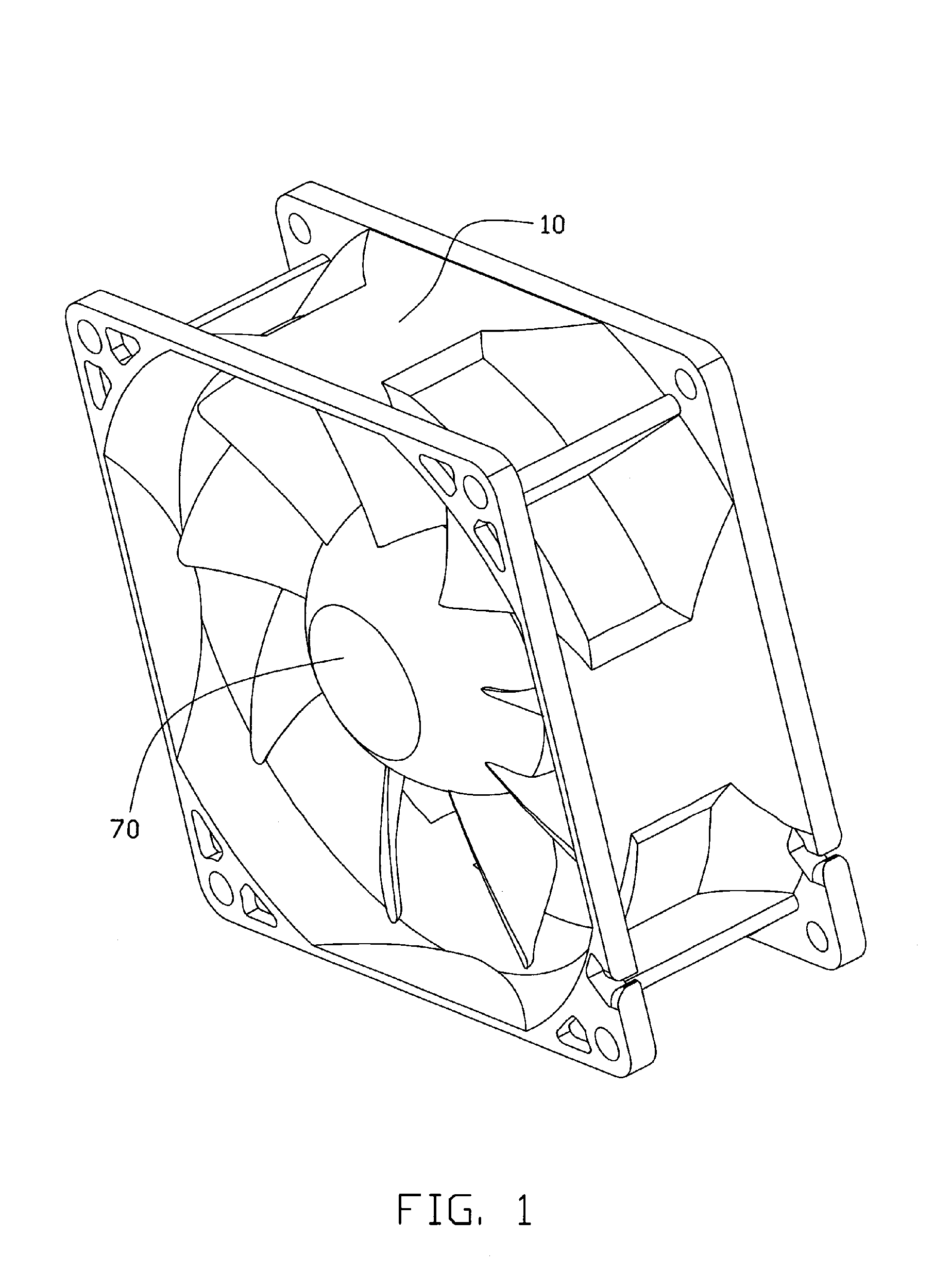
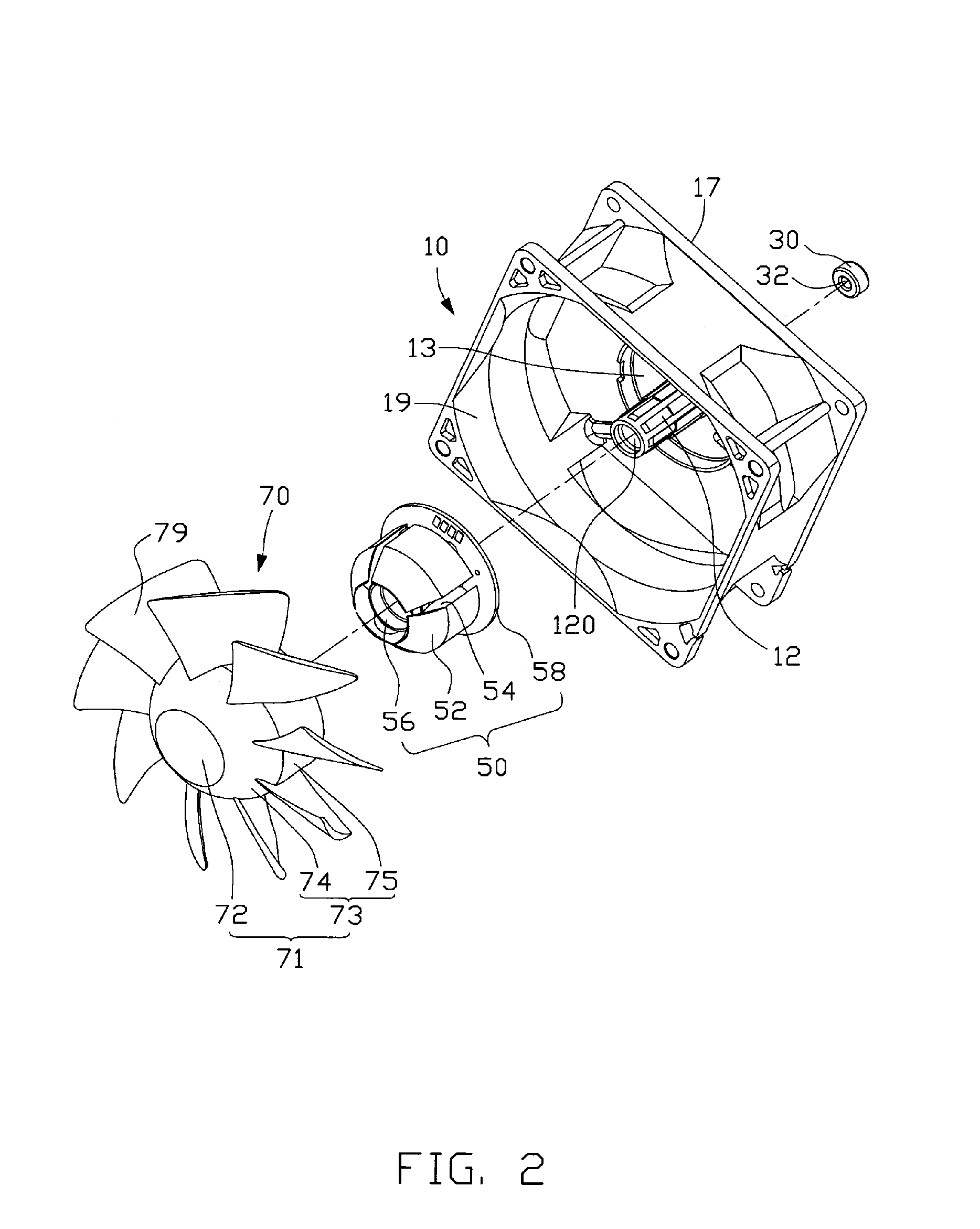
[0014] Referring to FIGS. 1 through 2, an electric fan according to a first embodiment of the present invention includes a rotor 70, a stator 50 relative to which the rotor 70 is rotatable, a frame 10 receiving the rotor 70 and the stator 50 therein, and a bearing 30 mounted in the frame 10 for supporting the rotor 70 in rotation.

[0015] Referring to FIGS. 3 through 4, the frame 10 is square shaped. An air inlet 19 and air outlet 17 are defined at two opposite sides of the frame 10, respectively. An airflow generated by the fan flows from the air inlet 19 to the air outlet 17. The frame 10 includes a base 13 adjacent to the air outlet 17. A central tube 12 extends upwardly from a central portion of the base 13. The central tube 12 defines a central hole 120 receiving the bearing 30 therein. An axial hole 32 is defined in the bearing 30.

[0016] The stator 50 is mounted around the central tube 12. The stator 50 includes a stator core 52, radial stator coils 54 wound around the stator ...


PUM


Abstract

An electric fan includes a frame (10) having a central tube (12) extending therefrom, a bearing (30) received in the central tube, a stator (50) mounted around the central tube, and a rotor (70) being rotatably supported by the bearing. The frame defines an air inlet (19) and an air outlet (17) at two different sides thereof. The stator includes a stator core (52) having a central cylinder (520). A plurality of radial posts (522) extends from the central cylinder. A plurality of magnetic poles (524) is formed at free ends of the posts. A plurality of stator coils (54) is wound around the posts. Each magnetic pole includes a lower portion (700) adjacent to the air outlet and an upper portion (60) adjacent to the air inlet. The upper portions expand radially along a direction from the air inlet to the air outlet.

Description

FIELD OF THE INVENTION [0001] The present invention relates to an electric fan, and more particularly to a motor for an electric fan. DESCRIPTION OF RELATED ART [0002] With the continuing development of electronic technology, electronic packages such as CPUs (central processing units) are generating more and more heat that requires immediate dissipation. Electric cooling fans are commonly used in combination with heat sinks for cooling CPUs. [0003] Referring to FIG. 5, a conventional electric cooling fan includes a stator 6, a rotor 8 rotatable with respect to the stator 6, and a fan housing 2 receiving the rotor 8 and stator 6 therein. The stator 6 is approximately cylinder-shaped and typically includes a stator core 62 and stator coils 64 wound around the stator core 62. The stator core 62 consists of layered yokes. Each yoke includes a ring shaped center portion and a plurality of pole members extending outwardly from the center portion for winding the coils thereon. To avoid the...

Claims


Application Information

Patent Timeline
Patent Type & Authority Applications(United States)
IPC IPC(8): H02K7/00H02K1/00H02K1/12F04B17/00
CPCH02K1/146H02K1/187H02K1/20H02K5/1675H02K7/14H02K9/06F04D25/064F04D25/0646
Inventor TUNG, CHAO-NIENYANG, CHIH-HAOHOU, CHUEN-SHU
Owner HON HAI PRECISION IND CO LTD
Why Eureka
Try Eureka