
System and method for conducting adaptive fourier filtering to detect defects in dense logic areas of an inspection surface

Active Publication Date: 2007-04-12
KLA TENCOR CORP
View PDF51 Cites 41 Cited by
  • Summary
  • Abstract
  • Description
  • Claims
  • Application Information

AI Technical Summary

Benefits of technology

[0016] One embodiment of the invention includes a dark field surface inspection system with an illumination source for directing a light beam onto a work piece to generate light scattering patterns from selected portions of the inspection surface. The system also includes a photodetector array arranged at a fourier plane to receive images of the light scattering patterns. Typically, the array comprises a two-dimensional array of light sensitive pixels. Circuitry for receiving the images and conducting adaptive fourier filtering of image data is part of the system. The circuitry employs adaptive filtering of image to selectively filter image pixels to generate filtered images. Additionally, the circuitry enables storage of the original image data before filtering. The filtered images can, for example, enhance signal to noise ratio in the filtered images.

Problems solved by technology

In particular, semiconductor wafer surfaces and associated masks are subject to such scanning and inspection.
As is known to those having ordinary skill in the art, defects are fairly uncommon in the inspected surfaces.
However, the consequences of such defects can be quite serious.
The presence of such defects on an inspection surface frequently cause a variation from the ordinary expected scattering pattern.
One of the problems in such dark field scanning is that for some surfaces the ordinary scattering pattern includes substantial regions of very bright signal.
This bright signal can make the process of defect detection much more difficult as defects also produce bright signals.
A problem with such prior art systems is that they have difficulty discerning defect scatter from ordinary scatter generated by a patterned surface.
Even in systems which employ die-to-die comparison, small variations in the surface pattern and the resulting variation in scattering can mislead the system into falsely identifying a defect.
Thus, portions of the (otherwise defect-free) patterned surface give false readings, as if they had defects in the surface.
One of the limitations of Fourier filtering based instruments is that they can only inspect areas with repeating patterns (for example, arrays of memory cells) or blank areas.
Critically, Fourier filtering of the type previously described is not useful for inspecting non-uniform surfaces like random logic areas.
This poses a significant fundamental limitation on the technology.
However, even with such die-to-die comparison, conventional technologies still need Fourier filtering to obtain good sensitivity in the repeating array areas.
As a result, either small particles in the array areas cannot be seen due to saturation, or small particles in the peripheral areas cannot be detected due to insufficient signal strength.
Although prior art techniques are relatively capable of detecting particle type defects, their sensitivity to pattern defects is very poor.
Additionally, since filtered images are usually dark without circuit features, it is not possible to do an accurate die-to-die image alignment, which is necessary for achieving good cancellation in a subtraction algorithm.
One solution is to use an expensive mechanical stage of very high precision, but even with such a stage, due to the pattern placement variations on the wafer and residual errors of the stage, the achievable sensitivity is limited roughly to particles that are 0.5 μm and larger.
This limit comes from the alignment errors in die-to-die image subtraction.
Additionally, the filtering makes it difficult to detect defects in certain regions of the surface.
Moreover, as surface patterns become more complicated (as is the case in modern VLSI circuit structures), the patterns become more complex, and more filtering must be implemented.
Additionally, although Fourier filtering can be extremely effective in filtering light scattered by regularly repeating array areas (e.g., memory cells), there is currently no similar technique that can be applied to areas of the wafer where the surface pattern is not regular and repeating.
Unlike memory areas (which feature repeating surface patterns), areas without repeating surface patterns are far more difficult to filter.
As a result, it is no longer practical to insert a fixed filter to selectively block light scattering caused by the surface pattern.
Heretofore, there has not been a tool or methodology of providing fourier filtering of data obtained in dense logic areas or other surface areas having non-repeating surface patterns.

Method used


Image

  • System and method for conducting adaptive fourier filtering to detect defects in dense logic areas of an inspection surface
  • System and method for conducting adaptive fourier filtering to detect defects in dense logic areas of an inspection surface
  • System and method for conducting adaptive fourier filtering to detect defects in dense logic areas of an inspection surface

Examples


Embodiment Construction

[0033] The present invention has been particularly shown and described with respect to certain embodiments and specific features thereof. The embodiments set forth herein below are to be taken as illustrative rather than limiting. It should be readily apparent to those of ordinary skill in the art that various changes and modifications in form and detail may be made without departing from the spirit and scope of the invention.

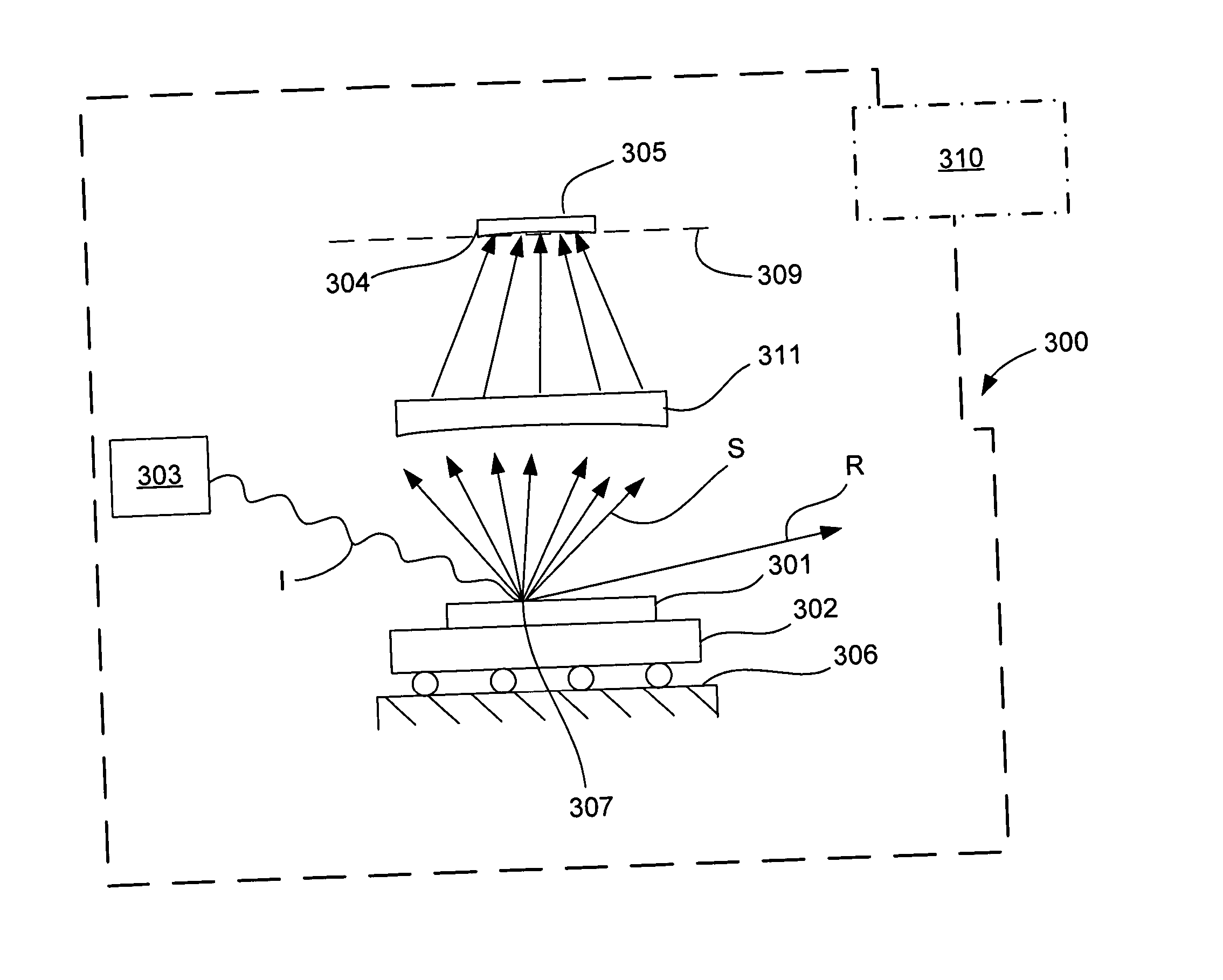
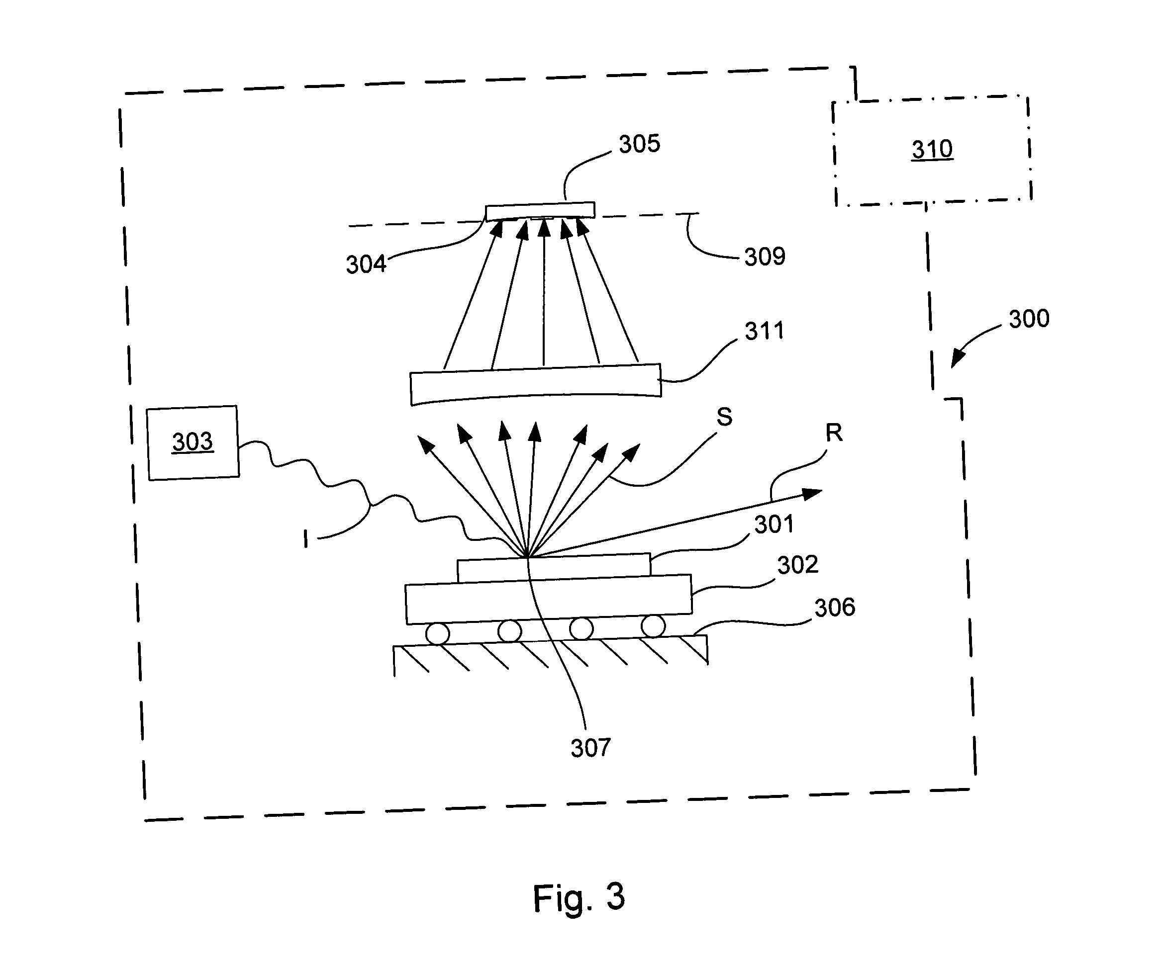
[0034] In general, adaptive filtering in accordance with the principles of the invention works as follows. A light beam is directed onto a target and scattered into a scattering pattern. The scattering pattern is collected by a photodetector array in a fourier plane to form an image of the pattern. The brightest pixels of the pattern are adaptively filtered out. And the remaining pixels are processed to detect defects. Because these brightest pixels change for each point on the inspection surface, there is a need for a highly adaptive filtering system that is ...


PUM


Abstract

A dark field surface inspection tool and system are disclosed herein. The tool includes an illumination source capable of scanning a light beam onto an inspection surface. Light scattered by each inspection point is captured as image data by a photo detector array arranged at a fourier plane. The images captured are adaptively filtered to remove a portion of the bright pixels from the images to generate filtered images. The filtered images are then analyzed to detect defects in the inspection surface. Methods of the invention include using die-to-die comparison to identify bright portions of scattering patterns and generate unique image filters associated with those patterns. The associated images are then filtered to generate filtered images which are then used to detect defects. Also, data models of light scattering behavior can be used to generate filters.

Description

RELATED APPLICATIONS [0001] This application claims priority to U. S. patent application entitled Surface Inspection System and Method For Using Photodetector Array to Detect Defects In Inspection Surface” filed on Dec. 9, 2002 having Ser. No 10 / 315,713 by inventors Evan R. Mapoles et al., and also claims priority to U.S. Provisional Patent Application Ser. No. 60 / 414,206, entitled “Darkfield Inspection System Having Photodetector Array”, by inventors Christopher F. Bevis et al., filed on Sep. 27, 2002 the content of which are both incorporated by reference. [0002] This application is related to the concurrently filed U.S. patent application entitled “Darkfield Inspection System Having Photodetector Array”, by inventors Christopher F. Bevis et al., Attorney Docket No. KLA1P084A / P1011, which is hereby incorporated by reference.TECHNICAL FIELD [0003] The invention described herein relates generally to surface inspection and testing. In particular, the invention relates to devices and ...

Claims


Application Information

Patent Timeline
IPC IPC(8): G01N21/88
CPCG01N21/47G01N21/95607G01N21/95623G01N2021/8822
Inventor MAPOLES, EVAN R.CHEN, GRACE H.BEVIS, CHRISTOPHER F.SHORTT, DAVID W.
Owner KLA TENCOR CORP
Features
  • Generate Ideas
  • Intellectual Property
  • Life Sciences
  • Materials
  • Tech Scout
  • Unparalleled Data Quality
  • Higher Quality Content
  • 60% Fewer Hallucinations
Learn More