[0006] Embodiments of the present invention provide for an improved localization of a mobile WLAN client, located within a WLAN network, on the basis of
scene analysis, to the effect that as precise a localization of the WLAN client within the WLAN network as possible is permitted on the basis of field-strength measurements of surrounding WLAN stations, using a justifiable technical expenditure.
[0008] Embodiments of the present invention provide for an enormous improvement in the accuracy of the estimated position of the WLAN client using only a few static reference points, for only a few static reference points, which are determined by initial measuring of field strengths at known spatial coordinates, are sufficient as a starting condition. According to a design approach of an embodiment of the present invention, the further reference points leading to the high accuracy are ascertained in self-learning fashion as dynamic reference points. A spatially precise indoor navigation solution is possible on this basis. Using an embodiment of the present invention, first attempts have already yielded extremely
usable results after a
training phase of approximately 3-4 communications per dynamically set reference point. Hit probabilities, i.e., the probability that the client is at the calculated position, for sufficiently trained regions in the area of 100 communications per dynamic reference point, are nearly 99%. If the WLAN client is not moving faster than 1.3 meters / second, then a difference of the distance between the estimated and the actual position of + / −2.5 meters is possible on average. Because the dynamic reference points are communicated over time, embodiment methods of the present invention also offer a certain degree of tolerance with respect to changes in the surroundings, such as rearrangement of furniture and plants, or moving persons. In embodiments of the present invention, the static reference points measured at the beginning are still necessary. They ensure the starting performance when using the design approach of the present invention. The number of static reference points is proportional to the starting performance and represents the
basic knowledge about the region of the WLAN network. The more client movements taking place in this region, the more precise the determinations of the WLAN clients' positions become. Another
advantage of the design approach according to the present invention is that the time-intensive, geometric measuring method for determining many static reference points is no longer necessary. Detailed information about a building or about a floor of a building is not necessary. For this reason, passing through obstacles such as walls or supporting pillars, which are not traversable, cannot be avoided. However, the dynamic map refinement counteracts this situation, since dynamic reference points can only be set at those locations at which a movement by the WLAN client is possible at all.
[0011] According to an embodiment of the present invention, a weighted shift of the center of gravity to the better matched reference point among the nearest matched data records of the static and dynamic reference points is carried out. This measure may improve the estimate of the position considerably.
[0015] A further embodiment provides for subdividing a region of the WLAN network into a grid having sectors, one dynamic reference position point being ascertainable per sector, in order to limit the number of dynamic reference position points. In this way, the computational expenditure is minimized enormously without the quality of the navigation deteriorating significantly. This measure ensures that the number of dynamically acquired reference points is kept in an easily comprehensible frame. The estimated client position is compared to the grid. The sector where the WLAN client is located according to the estimate is ascertained. The received values of the
field strength are then averaged into the center of gravity of the sector, taking a quality measure into account. The grid division of the region covered by the WLAN network is based on the WGS-84 reference coordinate
system, which permits a grid division of 0.2-3 meters. In a further embodiment, when using the dynamic map, a grid element spacing of 1 meter has proven to be effective. This grid element spacing represents an optimal compromise between precision and the
ambiguity of reference points when working with a grid element spacing that is too close.
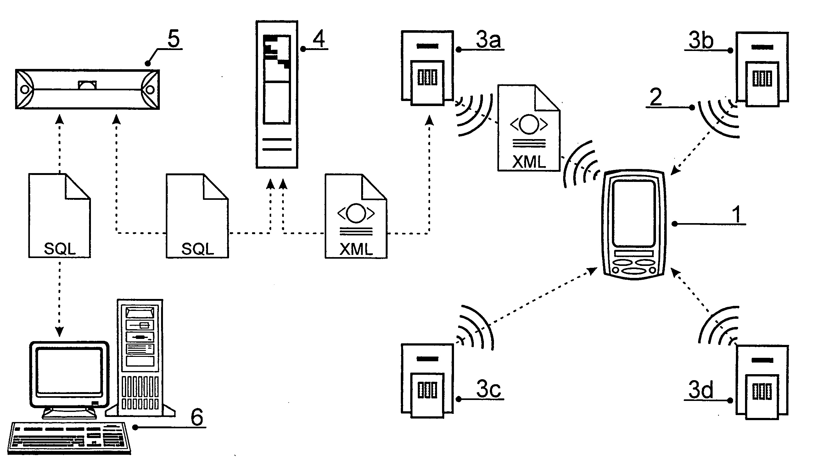
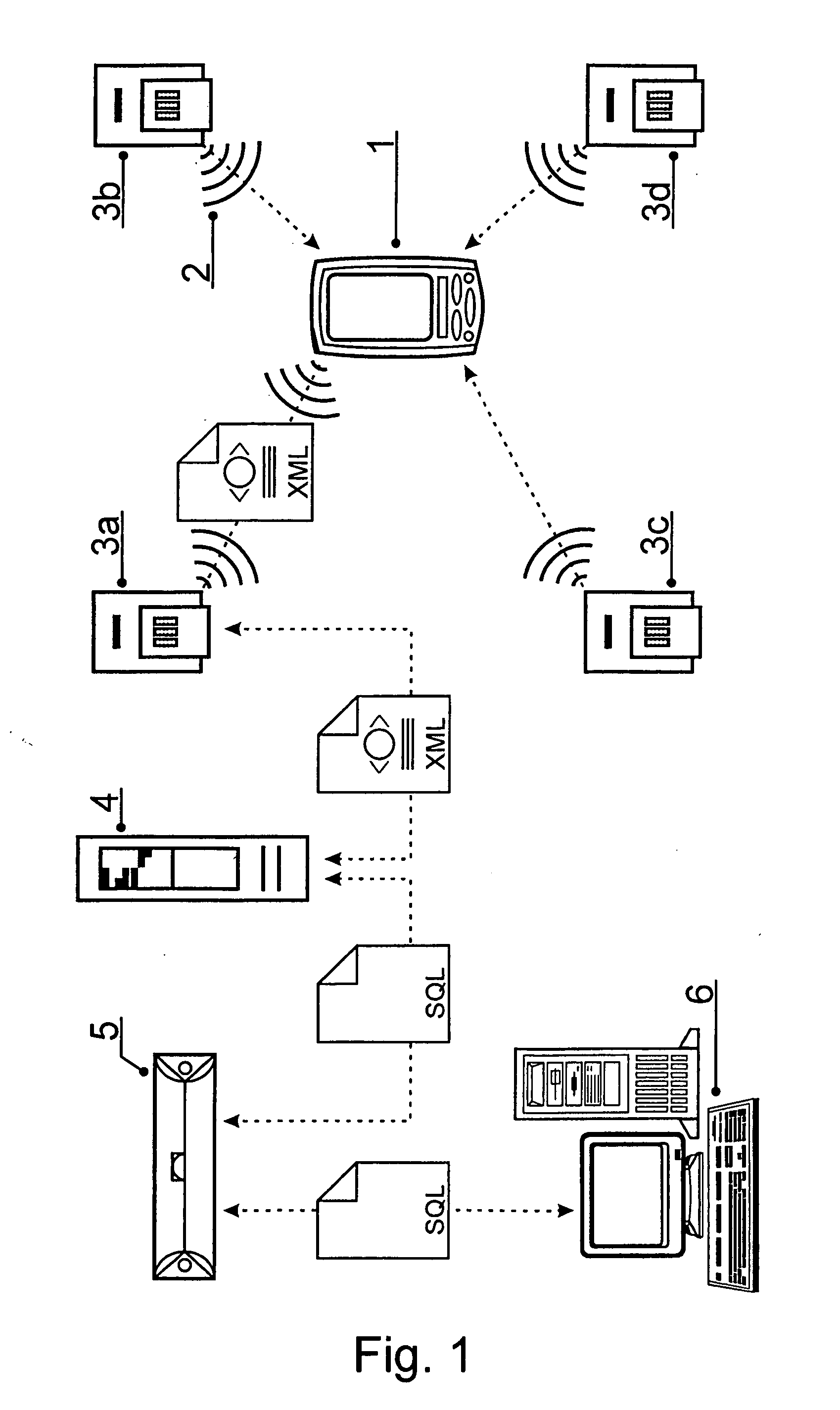
[0017] The method of the present invention for localization of a mobile WLAN client located within a WLAN network described in general above may be implemented in terms of hardware using a system in which the mobile WLAN client ascertains a few static reference points by measuring field strengths of the WLAN stations at known spatial coordinates and transmits them to a front-end
server which assigns the measured field strengths to the respective spatial coordinates in terms of data records. The data records resulting therefrom may be stored in a
database server connected to the front-end server. The additional dynamic reference points may be ascertained by measuring field strengths of WLAN stations received as a function of location, with the aid of the WLAN client moving through the region of the WLAN network, and feeding them to the front-end server. The front-end server assigns to these measured values, the respective spatial coordinates calculated for this purpose, which likewise may be stored as data records in the connected
database server. After adequate teach-in of a sufficient number of dynamic reference points, it is possible to precisely determine the position of a WLAN client within the region in that, in accordance with the field strengths ascertained by the WLAN client, the front-end server selects a plurality of nearest matched data records of static and dynamic reference points using the
scene analysis method, and subsequently localizes the client position by calculating the center of gravity.

