
System and method for whole body landmark detection, segmentation and change quantification in digital images

a whole body landmark and digital image technology, applied in image enhancement, image analysis, instruments, etc., can solve the problems of inaccurate and variable tumor delineation, manual and automatic tumor delineation and segmentation accuracy and variability, and often hinder data interpretation, so as to accurately quantify hot-spot volumes and improve the overall segmentation result.

Active Publication Date: 2007-04-12
SIEMENS HEALTHCARE GMBH
View PDF5 Cites 297 Cited by
  • Summary
  • Abstract
  • Description
  • Claims
  • Application Information

AI Technical Summary

Benefits of technology

[0014] Exemplary embodiments of the invention as described herein generally include methods and systems for discriminative learning-based framework that uses databases to guide the modeling and detection of landmarks (such as landmarks on the liver, kidney, lung, or bones) in whole-body CT, MRI or PET images, and an automatic method for determining the intensity threshold for hot-spot segmentation in PET images. Additional exemplary embodiments include a novel body-section labeling module based on spatial Hidden-Markov Models (HMM) to allow different processing policies to be applied in different body sections, a Competition Diffusion (CD) segmentation algorithm, which takes into account body-section information, and which converts the binary thresholding results to probabilistic interpretation and detects hot-spot region candidates, a recursive intensity mode-seeking algorithm that finds hot-spot centers efficiently, and given these centers, a clinically meaningful protocol to accurately quantify hot-spot volumes. Further exemplary embodiments include a CAD algorithm for automatically detecting suspicious volumes-of-interest (VOI) to the radiologist, an algorithm for bone segmentation based on PET-CT registration, and an algorithm for body context interpretation, which includes two components, body segmentation and body section labeling. Other exemplary embodiments include a multi-modal object segmentation (MMOS) that uses an initial segmentation based on data from one imaging modality to learn a model of the object that using data from additional modality(ies) to improve the overall segmentation result. More accurate and reproducible object delineation can be achieved as a result without the need for user intervention.

Problems solved by technology

These hot-spots typically lack well-defined edges, and therefore the choice of viewing window level or intensity threshold results in highly variable tumor delineation.
While tumor size is an important prognosis factor, both manual and automatic tumor delineation and segmentation accuracy and variability is an issue.
However, the interpretation of data has often been hindered by the inability to relate such information to specific anatomical regions.
The difficulty lies in the intrinsic large variations in anatomy; while normal anatomy from subjects vary, the variations are magnified in the condition of disease or abnormality.
From these results, it can be seen that the performance of these previous systems is not yet good enough for clinical use.
Furthermore, since these methods are mostly rule-based and explicitly use knowledge about specific organs or tissues in torso CT images, they are not easily adaptable to other imaging modalities such as PET and MRI, and to recognize a new anatomical structure of interest, a completely new image processing pipeline is required to be developed.
In some cases, if an internal structure of interest is small and exhibits large variations in the population, such as the kidneys, it may not be possible to develop a specific image-processing pipeline to target them at all.
As the amount of PET data generated every day increases, the burden on radiologists in reading and diagnosing these cases increases.
This may result in a negative effect, as the rate of overlooking anomalies can increase due to fatigue, and the risk of over-diagnosis may also rise.
Currently, there are no known commercially available CAD tools for FDG-PET images.
From a clinical perspective, the main challenge in hot-spot detection and segmentation is that normal tissues also uptake different levels of FDG.
In addition, the shape, size, and location of tumors are unpredictable.
From a medical image processing perspective, there are further challenges in hot-spot detection and segmentation.
However, a global thresholding method with a fixed threshold often does not work well in practice, because some organs induce high FDG uptake but correspond to normal physiology.
However, accurate hot-spot detection and precise tumor volume quantification remain largely unsolved, due to intrinsic imaging pitfalls and artifacts in PET and the lack of ground truth for validating proposed algorithms.
However, methods and systems that rely solely on registration, especially those involving nonrigid registration, are not robust in the context of whole-body imaging such as in PET, PET / CT, because the deformations are usually large due to changes in patient positioning, articulated motion, etc., the number of variables to be recovered tend to be much larger than the number of available constraints, and computational costs are high.
Robust and accurate delineation of object boundaries remains a challenge, especially when noisy and low-resolution data such as PET images are involved.
Current systems involving manual or semi-automatic object segmentation require significant user interaction.
In clinical practice, this presents an additional burden on the physician and limits the patient throughput.
Moreover, manual object delineation has been shown to be less reproducible as compared to fully automated segmentation.
However, the difference in attenuation between tumor and healthy tissue in CT is low and segmentation algorithms often fail when used on CT data alone.

Method used


Image

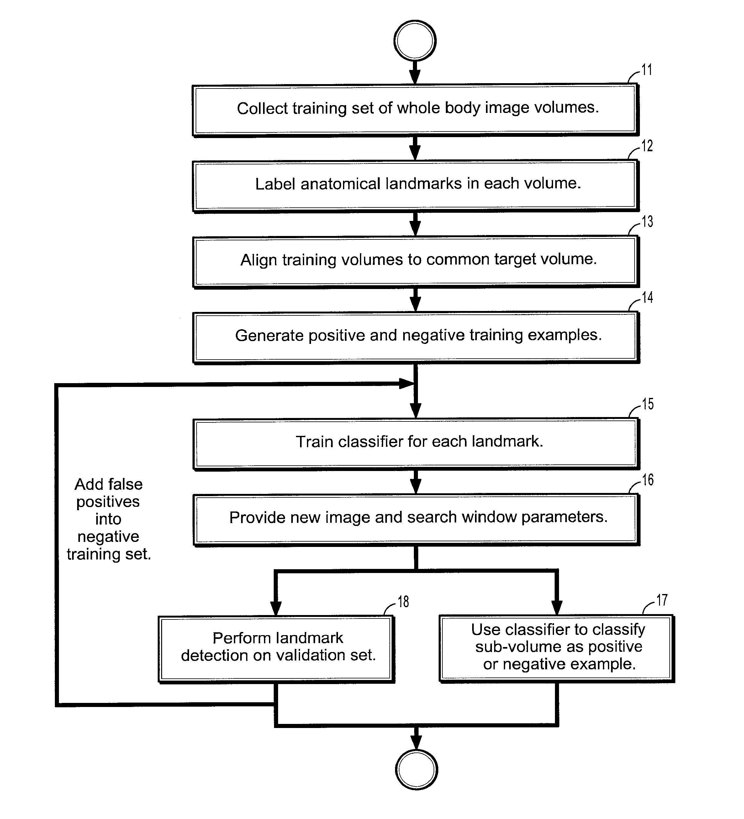
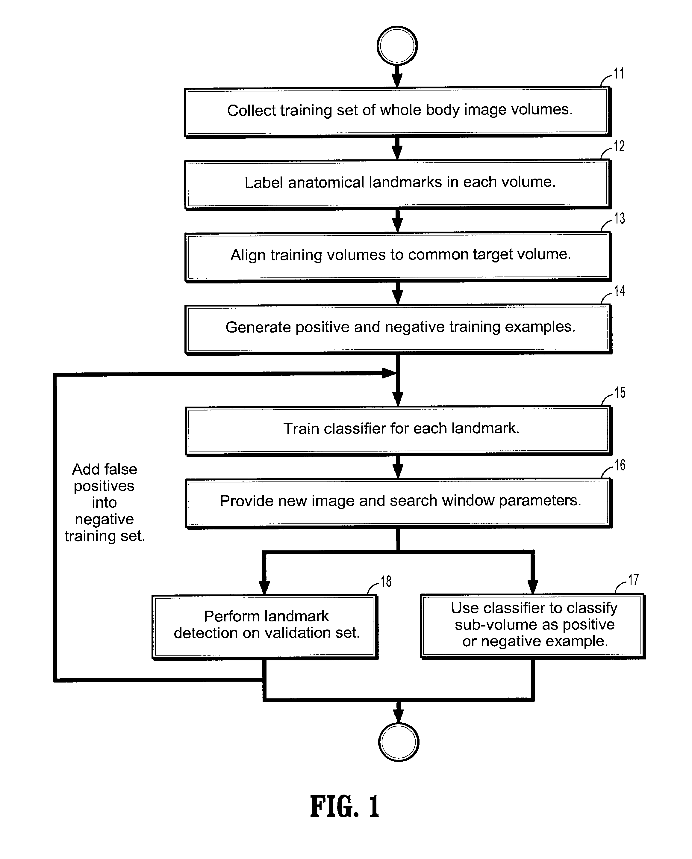
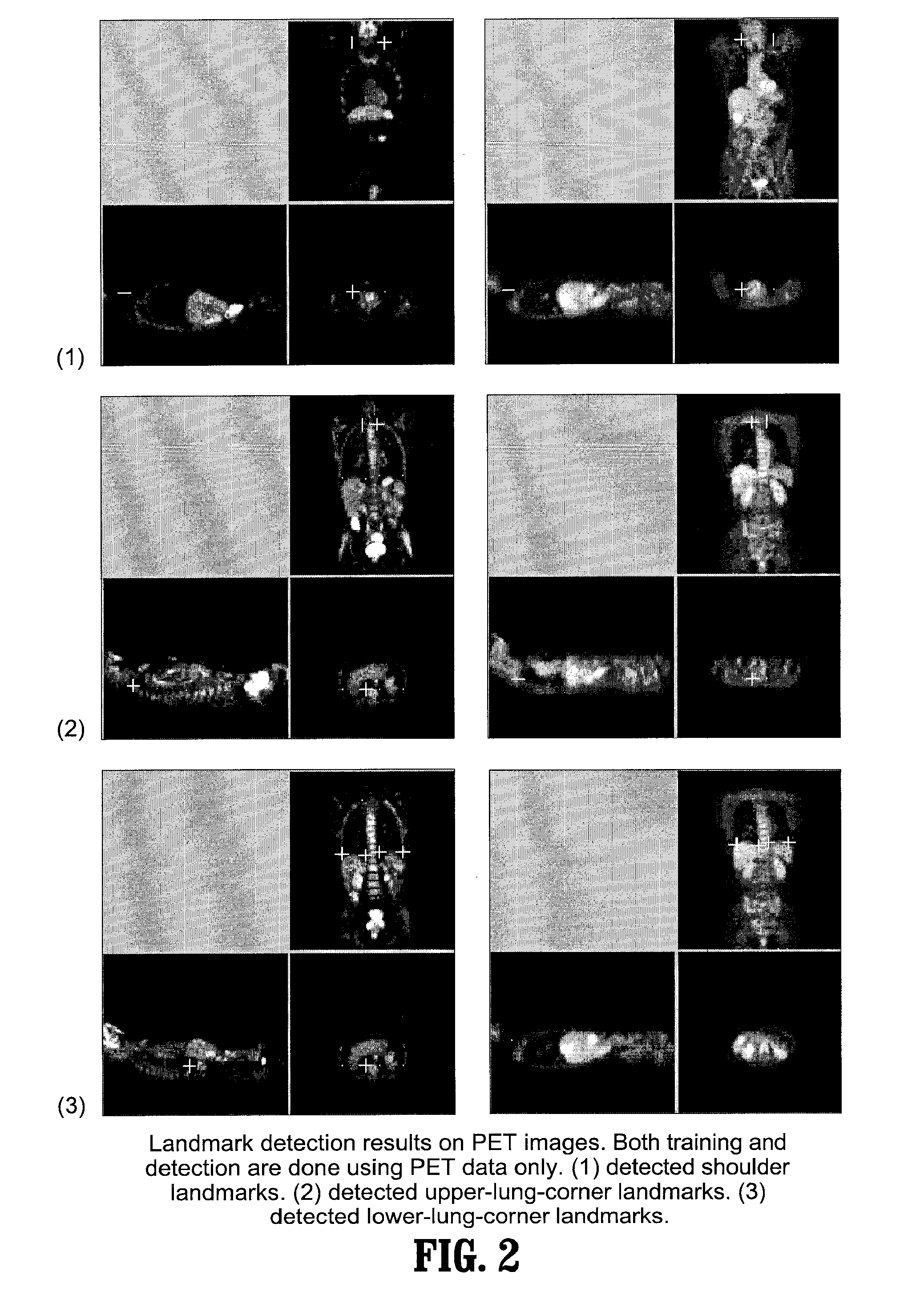
  • System and method for whole body landmark detection, segmentation and change quantification in digital images
  • System and method for whole body landmark detection, segmentation and change quantification in digital images
  • System and method for whole body landmark detection, segmentation and change quantification in digital images

Examples


Embodiment Construction

[0060] Exemplary embodiments of the invention as described herein generally include systems and methods for whole-body landmark detection, segmentation, and change quantification in single-mode and multi-mode medical images. Accordingly, while the invention is susceptible to various modifications and alternative forms, specific embodiments thereof are shown by way of example in the drawings and will herein be described in detail. It should be understood, however, that there is no intent to limit the invention to the particular forms disclosed, but on the contrary, the invention is to cover all modifications, equivalents, and alternatives falling within the spirit and scope of the invention.

[0061] As used herein, the term “image” refers to multi-dimensional data composed of discrete image elements (e.g., pixels for 2-D images and voxels for 3-D images). The image may be, for example, a medical image of a subject collected by computer tomography, magnetic resonance imaging, ultrasoun...


PUM


Abstract

A method for segmenting digitized images includes providing a training set comprising a plurality of digitized whole-body images, providing labels on anatomical landmarks in each image of said training set, aligning each said training set image, generating positive and negative training examples for each landmark by cropping the aligned training volumes into one or more cropping windows of different spatial scales, and using said positive and negative examples to train a detector for each landmark at one or more spatial scales ranging from a coarse resolution to a fine resolution, wherein the spatial relationship between a cropping windows of a coarse resolution detector and a fine resolution detector is recorded.

Description

CROSS REFERENCE TO RELATED UNITED STATES APPLICATIONS [0001] This application claims priority from: “Method and Apparatus for Automatic Threshold Selection and Segmentation of ‘hot-spots’ in PET Images”, U.S. Provisional Application No. 60 / 724,335 of Anna Jerebko, filed Oct. 6, 2005; “Method and Apparatus for Abnormality Detection in PET Images using a Probability Map of “Normal” Bright Spots in Normal Patients”, U.S. Provisional Application No. 60 / 724,379 of Anna Jerebko, filed Oct. 7, 2005; “Method and Apparatus for Hot-spot Segmentation and Change Quantification in PET and / or PET / CT Images”, U.S. Provisional Application No. 60 / 724,531 of Huang, et al., filed Oct. 7, 2005; “Method and Apparatus for Mode-seeking Region Growing with Application to Hot-spot Segmentation in PET Images”, U.S. Provisional Application No. 60 / 725,995 of Huang, et aL, filed Oct. 12, 2005; “Method and Apparatus for a Computer System For Automatic Hot-spots Detection and Segmentation in PET images”, U.S. Pro...

Claims


Application Information

Patent Timeline
IPC IPC(8): G06K9/00
CPCG06T7/0028G06T7/0038G06T7/0091G06T7/0097G06T2207/10072G06T2207/20016G06T2207/20081G06T2207/20164G06T2207/30004G06T2207/30204G06T7/33G06T7/38G06T7/155G06T7/174
Inventor HUANG, XIAOLEIZHOU, XIANGJEREBKO, ANNAKRISHNAN, ARUNGUAN, HAIYINGKUBOTA, TOSHIROPOTESIL, VACLAV
Owner SIEMENS HEALTHCARE GMBH
Learn More