
Valve for intravenous catheter

a valve and catheter technology, applied in the field of valves, can solve the problems of blood clot being injected into the patient, unfavorable movement of fluid, and disconnection of syringe or device, and achieve the effect of facilitating fluid administration and reducing the risk of blocking the flow path by clotting

Inactive Publication Date: 2007-04-12
SPAN-AMERICA MEDICAL SYSTEMS
View PDF7 Cites 272 Cited by
  • Summary
  • Abstract
  • Description
  • Claims
  • Application Information

AI Technical Summary

Benefits of technology

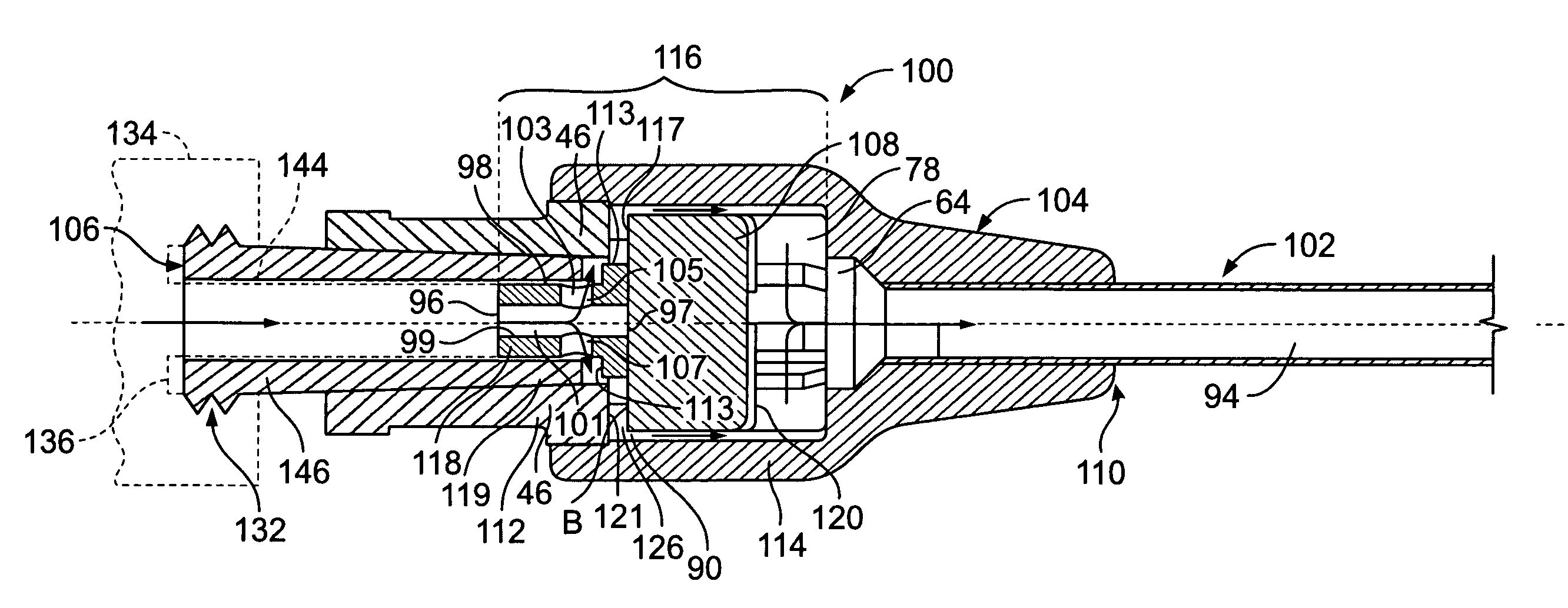
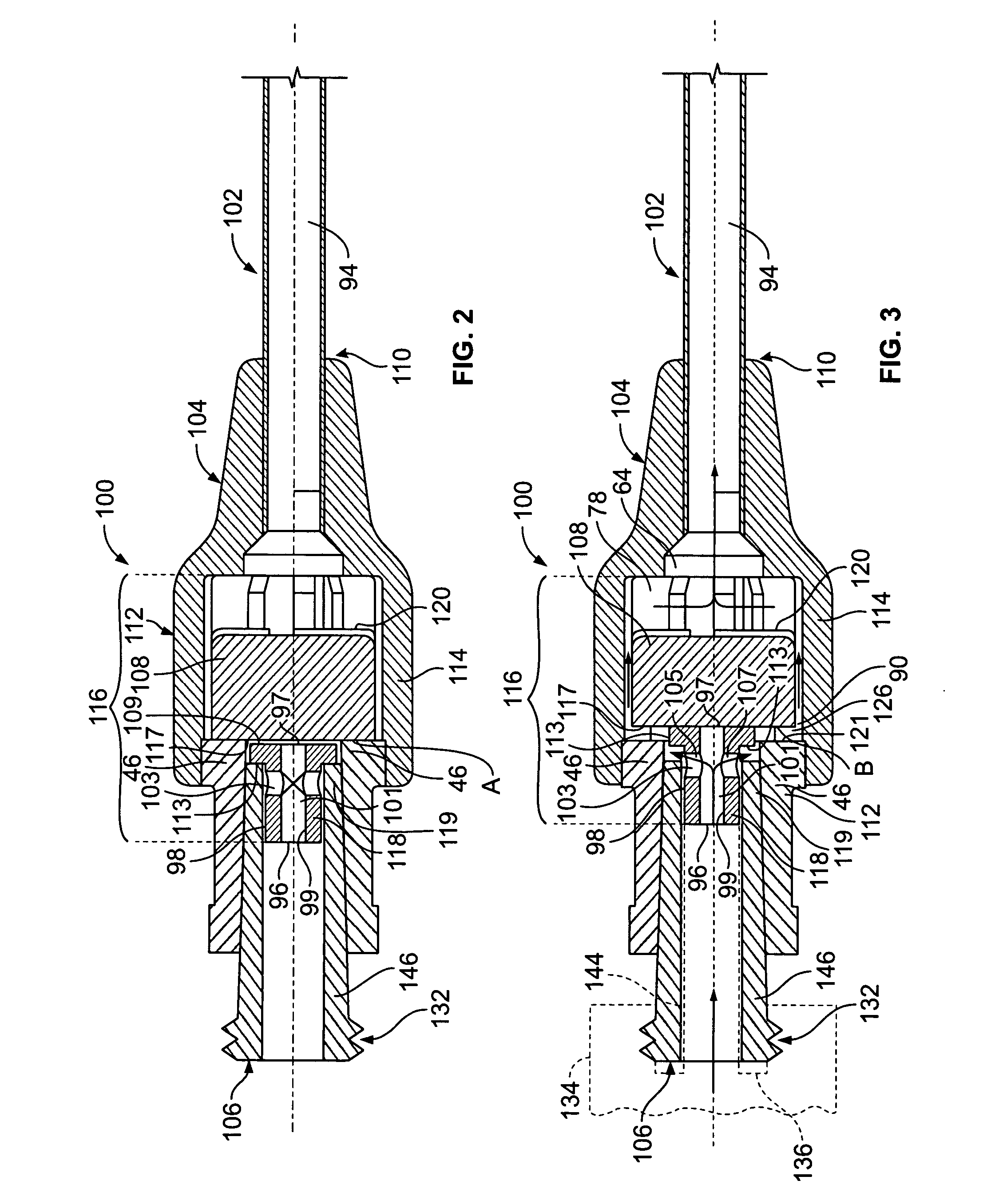
[0008] The invention is directed to a valve assembly in an intravenous catheter that facilitates the administration of fluid to a patient through the intravenous catheter by a needleless device. The valve assembly of the present invention contains means for creating a positive displacement of fluid from the intravenous catheter at a time when a needleless device is removed from the valve assembly following its connection to the valve assembly. By creating a positive displacement of fluid from the catheter and preventing reflux into the catheter, the risk of blocking the flow path by clotting is substantially reduced without the use of additional drugs.

Problems solved by technology

With many conventional valves, a problem arises when the syringe or device is disconnected from the valve.
In the medical setting, this movement of fluid is very undesirable.
A serious problem may result in that this blood may clot and clog the catheter near its tip, rendering it inoperable, and may even result in a clot of blood being injected into the patient.
The risk of blood clogging the catheter is significantly increased in catheters having a small diameter (e.g., 24 gauge).
Because these catheters have a very small internal passage, even a small suction force may draw a significant amount of fluid back through a catheter toward the valve, introducing blood into the catheter tip.
Saline and heparin, however, are not always available to flush the flow path when removing the syringe or device.
Finally, the use of saline or heparin does not provide a consistent solution to the problem because the user cannot be sure that the bodily fluids that were drawn toward the valve did not block the flow path, rendering the catheter unusable.

Method used


Image

  • Valve for intravenous catheter
  • Valve for intravenous catheter
  • Valve for intravenous catheter

Examples


Embodiment Construction

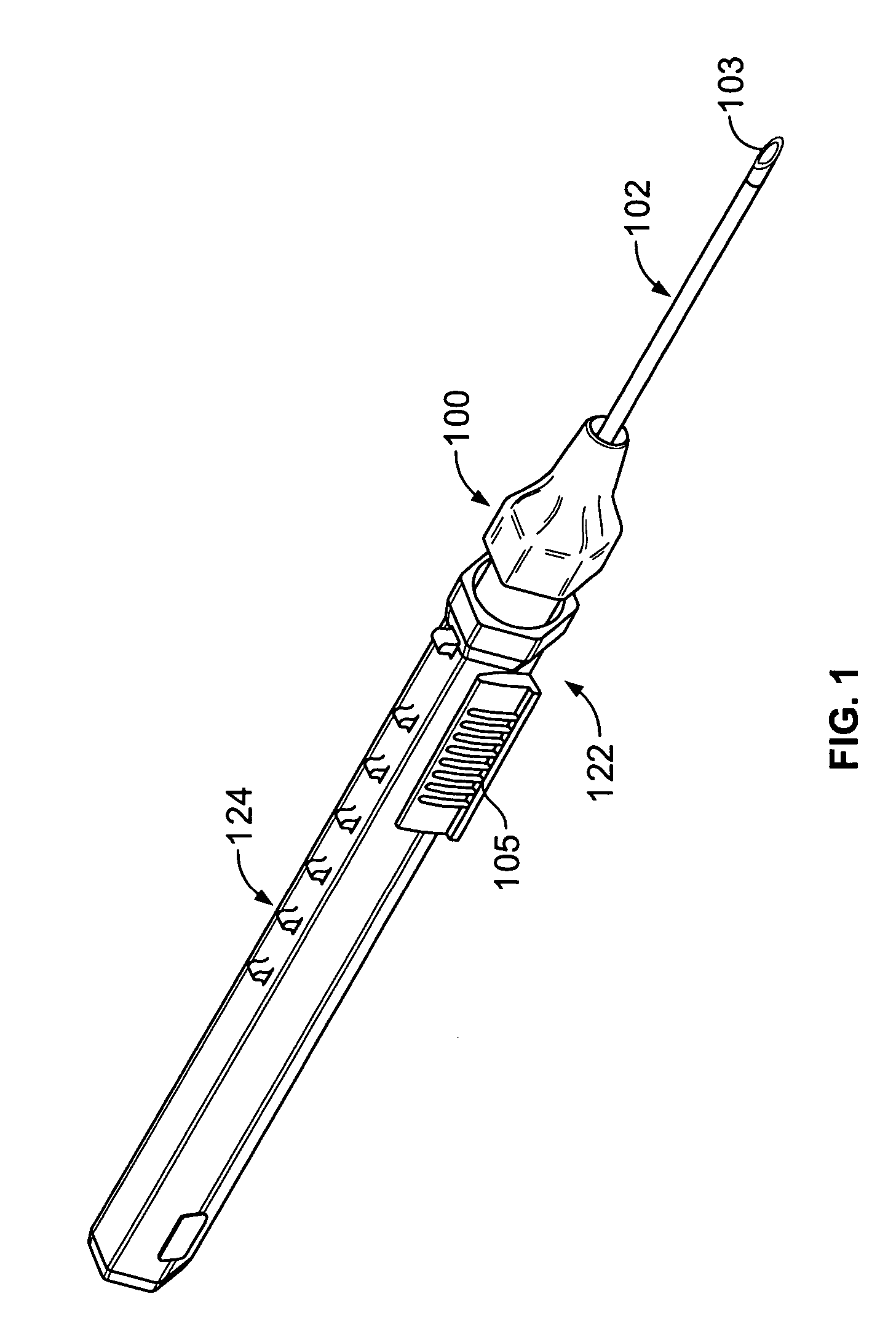
[0031] As shown in FIG. 1, the intravenous catheter assembly 122 of the present invention has a needle protector 124, a catheter hub 100, an over-the-needle plastic catheter tubing 102, and a hollow bore needle 103. The needle protector 124 connects to the catheter hub 100 using a mating luer system of threaded interlocking pieces. These threads are typically constructed to conform to American National Standard Institute No. ANSI / HIMA MD70.1-1983 or ISO 594 / 2-1998 relating to luer lock fittings. Other connection systems, however, may be used to connect the needle protector 124 and the catheter hub 100 without departing from the spirit and scope of the present invention.

[0032] One using the intravenous catheter assembly 122 locates a blood vessel on the patient's body. The needle 103 and catheter tubing 102 are inserted through the skin and blood vessel of the patient. Once the needle is in the blood vessel, blood “flashes” through the needle fluid passageway or catheter tubing 102....


PUM


Abstract

The present invention is directed to a valve assembly in an intravenous catheter that facilitates the administration of fluid to a patient through the intravenous catheter by a needleless device. The valve assembly of the present invention contains means for providing a positive displacement of fluid from the catheter at a time when a needleless device is removed from the valve assembly following its connection to the valve assembly.

Description

FIELD OF THE INVENTION [0001] The invention is directed to valves, and more specifically, to valves in medical devices that control fluid flow. BACKGROUND OF THE INVENTION [0002] Intravenous catheters are medical devices for administering intravenous fluids, medications, and blood products. Intravenous catheters may also be used for aspirating blood for testing or donation. An intravenous catheter generally consists of a hollow-bore needle and a close-fitting, over-the-needle plastic catheter tubing used to access the lumen of a blood vessel in a patient. After the needle and catheter are inserted into the blood vessel, the needle is retracted from the patient and discarded, leaving only the catheter in the blood vessel. The catheter contains a catheter hub through which fluids, medications, and blood may be injected or through which blood samples may be taken from the patient. Needles were originally employed for accessing the catheter hub, but now needle-free injection sites or va...

Claims


Application Information

Patent Timeline
IPC IPC(8): A61M5/178
CPCA61M25/0606A61M39/26A61M2005/3252A61M2039/263A61M2039/266
Inventor O'REAGAN, JAMESMOSLER, THEODORE J.
Owner SPAN-AMERICA MEDICAL SYSTEMS
Learn More