Conductive Adhesive Attachment of Capacitor Terminals

a technology of conductive adhesive and capacitor, which is applied in the direction of wound capacitors, fixed capacitors, fixed capacitor details, etc., can solve the problems of reducing the electrical performance of metallized or film/foil capacitors, reducing the electrical performance of capacitors, and reducing the current capacity. , to achieve the effect of high reliability

Inactive Publication Date: 2007-04-19
SB ELECTRONICS
View PDF10 Cites 14 Cited by
  • Summary
  • Abstract
  • Description
  • Claims
  • Application Information

AI Technical Summary

Benefits of technology

[0008] One advantage of the present invention is that it enables terminal attachment to the end-spray metallization on a wound capacitor with no electrical or mechanical damage to the capacitor film.
[0009] Another advantage of the present invention is that it allows the fabrication of wound capacitors with the highest possible reliability in applications where extremes of average or pulse current are required.
[0010] Another advantage of the present invention is that it allows the use of physically large terminals and / or leads that would be impossible to attach to the capacitor in any other way.
[0011] Another advantage of the present invention is that it allows the capacitor to be installed in a system [such as, but not limited to, part of a power bus structure] such that no intermediary “terminations” are required. This flexibility of connection allows system level size reduction and performance improvements unavailable and / or impractical using alternative terminal attachment methods.

Problems solved by technology

The resulting electrical disconnection between the metallization and the end-spray metal layer leads to several problems.
After the capacitor terminals / leads are attached, the capacitor will have higher losses, lower current capability, and much less resistance to further metallization contact loss in applications where the capacitor is rapidly charged or discharged.
The solder process significantly limits the electrical performance of metallized or film / foil capacitors, especially as the ratio of contact damage to total contact surface increases.
The damage to capacitors with resistance-welded terminal attachment is reduced in proportion to the reduction in peak temperature excursion experienced by the film, but there remain problems for the same reasons described above.
This stored heat continues to inflict damage to the film directly beneath the lead and / or terminal attachment area, resulting in continued destruction of the electrical contact between the end-spray metal and the metallized film.
This results in melting of the film between the foil layers, causing permanent capacitor damage in regions that may be substantially removed from the lead and / or terminal attachment location(s).

Method used


Image

  • Conductive Adhesive Attachment of Capacitor Terminals
  • Conductive Adhesive Attachment of Capacitor Terminals
  • Conductive Adhesive Attachment of Capacitor Terminals

Examples


Embodiment Construction

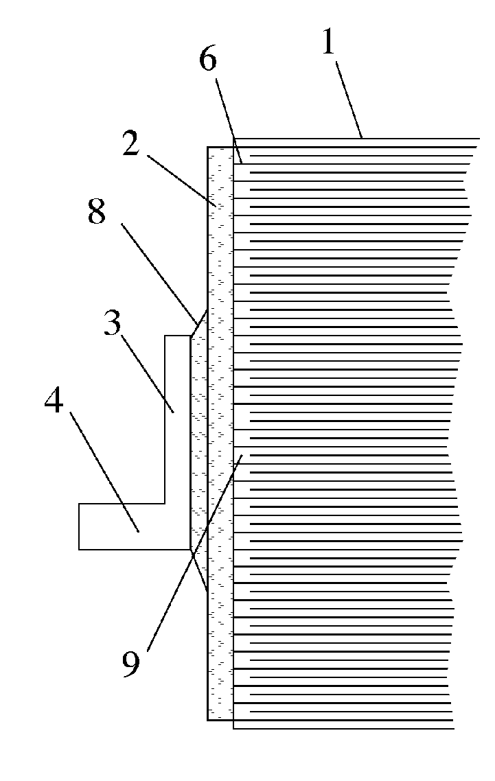
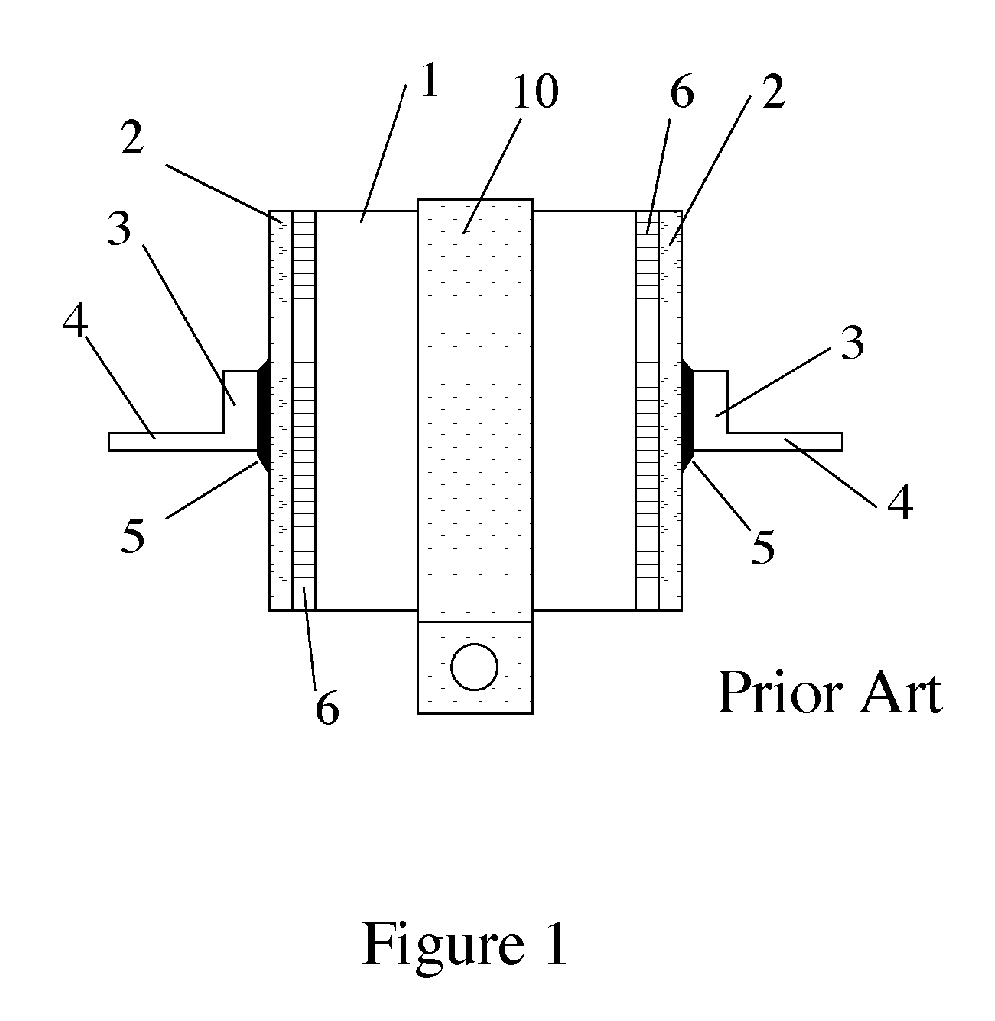
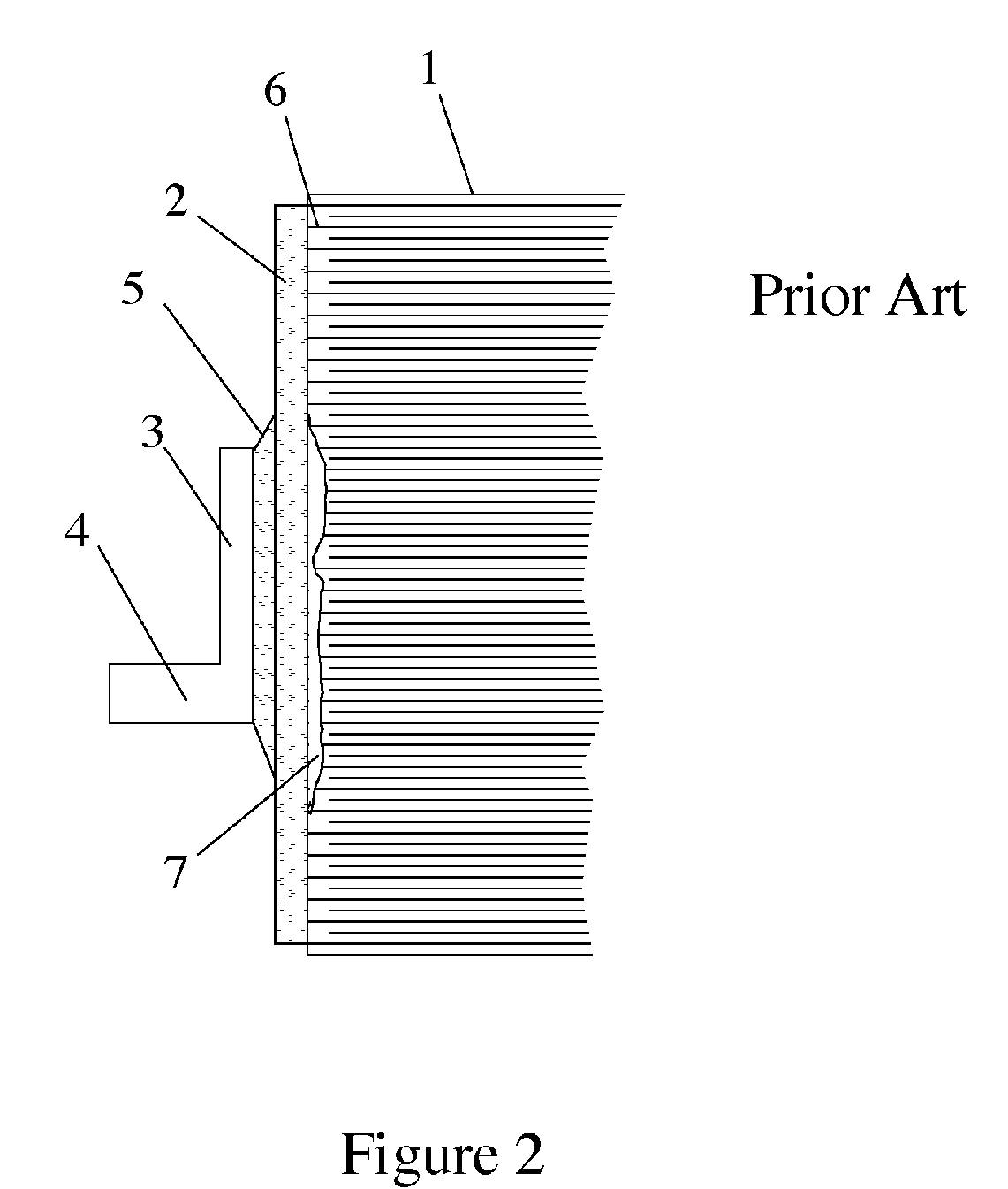
[0016]FIG. 1 is a drawing of prior art showing one end of a tubular shaped wound metallized film capacitor. The body of the capacitor 1 is comprised of multiple windings of metallized insulating film or multiple windings of a composite stack consisting of insulating film and metallic foil. At each end of the capacitor body, the metallized film or the film and metallic foil form an electrical contact region 6. An end-spray metallization layer 2 is applied using well-known processes to each electrical contact region 6 to form an intimate electrical connection with the plurality of conducting layers comprising the capacitor body 1. The end-spray metallization is preferably applied over the entire area of each end of the capacitor. An electrically conductive termination is comprised of a terminal foot 3 electrically connected with the terminal extension 4. Alternatively, an electrical lead can be used in place of the terminal 3 and 4. The terminal foot 3 is electrically and mechanically...


PUM

PropertyMeasurementUnit
thicknessaaaaaaaaaa
lengthaaaaaaaaaa
outer radiusaaaaaaaaaa

Abstract

An improved electrical terminal attachment process for a wound polymer film/foil or metallized film capacitor is described that minimizes thermal damage to the capacitor structure and improves the current carrying capability of the capacitor. The process employs an electrically conductive adhesive that can be cured at low temperatures. The disclosed process improves the reliability of the capacitor when used at high RMS or pulsed currents. It also enables capacitor application structures with reduced equivalent series inductance that would be otherwise difficult or impossible to fabricate.

Description

CROSS REFERENCE TO PRIOR APPLICATION [0001] This application claims priority of U.S. Provisional Application Ser. No. 60 / 596,708 filed Oct. 14, 2005 and entitled “Conductive Adhesive Attachment of Capacitor Terminals,” the subject matter of which is incorporated herein by reference.FIELD OF INVENTION [0002] The present invention relates to a process for attaching electrical terminals that results in a polymeric metallized film or film / foil wound capacitor with increased current carrying capability and reduced parasitic impedance, making it useful for high current applications. DESCRIPTION OF THE PRIOR ART [0003] Wound film capacitor construction is well known prior art. In a metallized film wound capacitor, the metallized film is wound up in a roll, with each film layer extending to one side of the wound section. In a film / foil wound capacitor, a metallic foil is placed next to the film and the composite of film and metallic foil is wound up in a roll. Connection to the metallizatio...

Claims


Application Information

Patent Timeline
Patent Type & Authority Applications(United States)
IPC IPC(8): H01L21/00
CPCH01G4/18H01G4/228H01G4/232H01G4/2325Y10T29/41H01G4/32Y10T29/417Y10T29/49101H01G4/30
Inventor HOSKING, TERRY ALAN
Owner SB ELECTRONICS
Why Eureka
Try Eureka